
Amplifier Circuits-Audio
Index 5
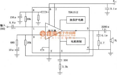
TDA1512, TDA1512Q 20WHi-Fi audio power amplifier circuit diagram
Published:2011/8/31 2:36:00 Author:Rebekka | Keyword: 20WHi-Fi , audio power amplifier
View full Circuit Diagram | Comments | Reading(2464)
LM2002, LM2002A 8W Audio power amplifier circuit diagram
Published:2011/8/31 2:41:00 Author:Rebekka | Keyword: 8W , Audio power amplifier
LM2002/2002Ais theaudio power amplifier IC. It uses 5-pin single in-line plastic package. The features of the two ICs are large output power, less distortion, low noise, small number of external components, high input impedance, low noise of power shock etc. LM2002 has limiting current and thermal shutdown protection circuit; LM2002A has a high voltage protection. The maximum instantaneous power supply voltage is up to 40V. They are suitable for the audio power amplifier of car audio systems, ordinary portable or desktop recorder. The BTU circuit is shown as the chart. (View)
View full Circuit Diagram | Comments | Reading(1525)
The integrated circuit diagram of two-channel audio power amplifier
Published:2011/9/18 21:16:00 Author:Ecco | Keyword: Two-channel audio , power amplifier , integrated circuit
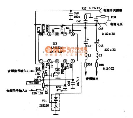
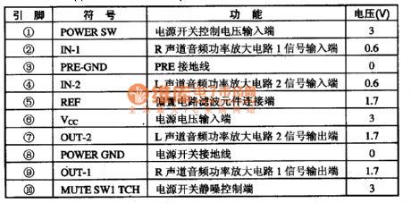

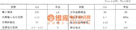
LA4533M is the two-channel audio power amplifier integrated circuit produced by Sanyo of Japan, and it is widely used in pocket radio, Walkman and other low-voltage, low-power audio system. 1. LA4533M internal block diagram and pin functions LA4533M manifold is mainly composed of two-way power amplifier circuit, power-off mute switch circuit, ripple filter circuit. The manifold internal block diagram is shown in Figure 1, the IC uses 10-pin dual flat plastic structure, and the integrated circuit pin functions and data are listed in Table 1.
(View)
View full Circuit Diagram | Comments | Reading(1507)
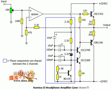
Fever headphone amplifier circuit diagram 1
Published:2011/9/2 1:18:00 Author:Ecco | Keyword: Fever headphone amplifier
View full Circuit Diagram | Comments | Reading(1018)
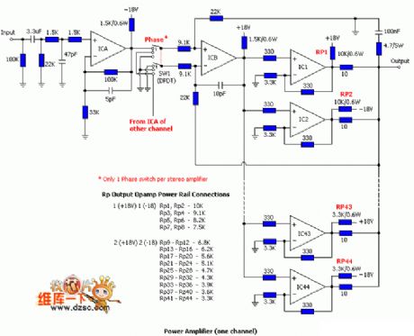
Fever headphone amplifier circuit diagram 2
Published:2011/9/2 1:17:00 Author:Ecco | Keyword: Fever headphone amplifier
View full Circuit Diagram | Comments | Reading(1443)
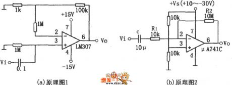
LM307, μA741 audio amplifier circuit diagram
Published:2011/9/9 1:58:00 Author:Ecco | Keyword: audio amplifier
View full Circuit Diagram | Comments | Reading(1768)
power amplifier(STK6153,STK3048) circuit of thick film integrated package
Published:2011/9/15 1:42:00 Author:chopper | Keyword: power amplifier, thick film, integrated package
The picture is a power amplifition circuit of thick film integrated package.Picture (a) shows that input signal is loaded to in-phase end of STK3048 through resistace-capacity coupling circuit(resistance is 33kΩ,capacitance is 4.7μF) and it is added to the base of power tube Q1,Q2 by its output end after it is amplified by thick film power amplifier STK3048.The power amplifier adopts dynatron 2N3055 and MJ2955.R1,R2(0.25Ω) are protective resistors of common emitter. Adjusting potentiometer RP can make power tube in the stage of classA,B,and at this time,the voltage drop of R1,R2 is about 10~13mV,the quiescent current of corresponding Q1 and Q2 is 40~50mA. (View)
View full Circuit Diagram | Comments | Reading(1542)
Frequency Synthesizer Circuit Diagram
Published:2011/9/14 0:26:00 Author:Zoey | Keyword: Frequency, Synthesizer Circuit Diagram
SIM8821XO2 -GOTO is a frequency synthesizer integrated circuit, it is widely used in Samsung's CDMA series cellphones, such as the Samsung A399 mobile phone.
1 Features
SIM8821XO2-GOTO integrated circuit contains the first local oscillator, the second local oscillator sampling and filtering circuit, and frequency synthesis data,start, clock circuits,phase detector power supply circuit, as well as some other auxiliary function circuits.
2 Pin Functions
Pin functions of SIM8821XO2 -GOTO IC have been listed in Table 1. (View)
View full Circuit Diagram | Comments | Reading(1147)
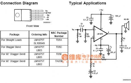
Lm1875T Hi-Fi 30w audio power amplifier circuit diagram 1
Published:2011/8/19 1:10:00 Author:Jessie | Keyword: Hi-Fi , 30w , audio power amplifier
View full Circuit Diagram | Comments | Reading(3317)
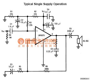
Lm1875T Hi-Fi 30w audio power amplifier circuit diagram 2
Published:2011/8/19 0:58:00 Author:Jessie | Keyword: Hi-Fi , 30w audio, power amplifier
View full Circuit Diagram | Comments | Reading(3862)
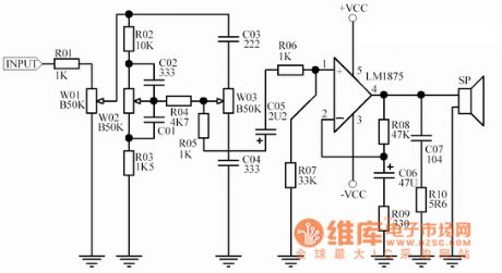
Lm1875T Hi-Fi 30w audio power amplifier circuit diagram 3
Published:2011/8/19 0:59:00 Author:Jessie | Keyword: Hi-Fi , 30w , audio power amplifier
View full Circuit Diagram | Comments | Reading(4557)
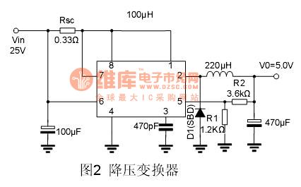
The step-down converter of MC34063 application circuit
Published:2011/8/13 2:01:00 Author:qqtang | Keyword: step-down converter, application circuit
View full Circuit Diagram | Comments | Reading(3400)
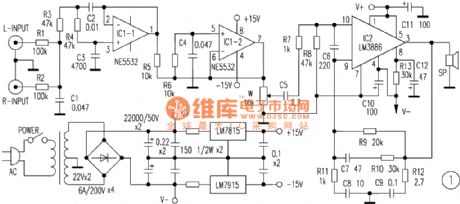
LM3886 Subwoofer circuit diagram
Published:2011/8/9 2:24:00 Author:Rebekka | Keyword: Subwoofer
View full Circuit Diagram | Comments | Reading(4259)
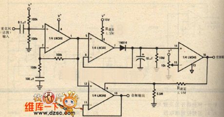
Voice switching and amplifier schematic diagram
Published:2011/8/11 1:43:00 Author:Ecco | Keyword: Voice switching , amplifier
View full Circuit Diagram | Comments | Reading(980)
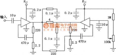
2 W x 2 power amplifier(LM1877)circuit
Published:2011/8/8 9:07:00 Author:Fiona | Keyword: 2 W x 2 power amplifier
Shown in the figure,the circuituses on,under symmetrical structure and has two way signal which is added respectively to the two op-amp non-inverting input ends of LM1877,its output end’s external way is same with the input end: it uses 2.7 Ω resistor and 0.1 u F to form the high frequency filter circuit to prevent the high frequency of self-excited; coupling capacitor Co (470 u F) and load resistor ZL (loudspeaker:8Ω) concert the output power into voice to output, and the magnitude of Co and ZL circuit is also determined to the circuit’s lower-cut-off frequency fL,the relationship between this three is: fL=1/(2πZLCo),corresponding to the parameters in the figure,its fL = 42 Hz.
(View)
View full Circuit Diagram | Comments | Reading(1557)
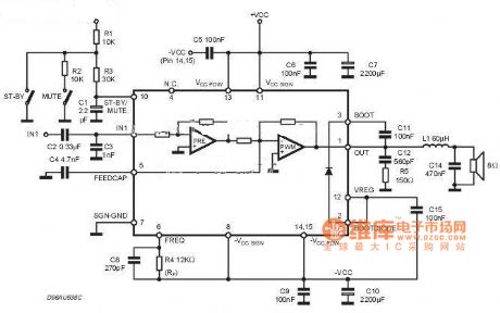
50W Hi-Fi Integrated Audio Power Amplifier (TDA1514A) Circuit
Published:2011/7/17 22:09:00 Author:Robert | Keyword: 50W, Hi-Fi, Integrated, Audio, Power Amplifier
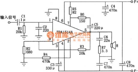
The picture shows the audio integrated power amplifier's typical application circuit composed ofTDA1514A. TDA1514A is a 50W Hi-Fi audio amplification IC produced by the Philips company. Its internal protection circuitsare complete, which means it has not only the general over-heating, output short circuit protection, but also the safe operating area protection. The circuit is also set up a silent switch to suppress the starting noise' appearance. In the circuit's design it is also considered the better ripple rejection and low offset with low thermal resistance. (View)
View full Circuit Diagram | Comments | Reading(5668)
Integrated audio amplifier circuit diagram
Published:2011/8/4 1:28:00 Author:Ecco | Keyword: Integrated audio amplifier
View full Circuit Diagram | Comments | Reading(1017)
BROADBAND_WITH_GAIN_OF_1350
Published:2009/7/10 1:43:00 Author:May
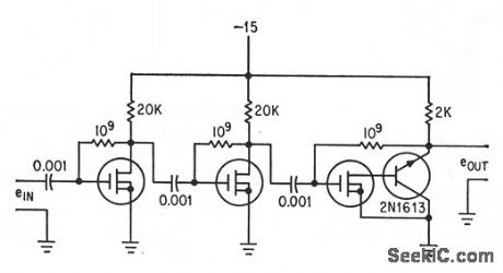
Metal oxide semkonductor transistors (p-mosts) in Darlington contguration give high input impedance and low output impedance from 5 cps to 72 kc.-F. M. Wanklss, Novel Field-Effect Devke Provides Broadband Gain, Electronics, 36A4, p 30-33. (View)
View full Circuit Diagram | Comments | Reading(814)
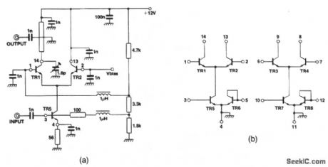
65_watt_AF_power_amplifier_using_an_ECG1078_chip_powered_by_±12_volt_supplies
Published:2009/7/20 4:28:00 Author:Jessie

6.5-watt AF power amplifier using an ECG1078 chip powered by ±12-volt supplies. Frequency response is from 100 hertz to 20 kilohertz (courtesy GTE Sylvania Incorporated). (View)
View full Circuit Diagram | Comments | Reading(962)
900_MHz_gain_controlled_amplifier
Published:2009/7/23 22:24:00 Author:Jessie
This circuit shows an SL2365 transistor array connected as a gain-controlled amplifier. The transistor-array connections are shown in Fig. 2-35B.The collector load of TR1 is a transformer that is composed of a 14-mm length of 75-Ω stripline resonated with a 1- to 6-pF variable capacitor. The transformer secondary is a small loop of stiff wire that is grounded at one end and located a few mm above the stripline. The noise figure at full gain is 9 dB. (View)
View full Circuit Diagram | Comments | Reading(1096)
| Pages:5/13 12345678910111213 |
Circuit Categories
power supply circuit
Amplifier Circuit
Basic Circuit
LED and Light Circuit
Sensor Circuit
Signal Processing
Electrical Equipment Circuit
Control Circuit
Remote Control Circuit
A/D-D/A Converter Circuit
Audio Circuit
Measuring and Test Circuit
Communication Circuit
Computer-Related Circuit
555 Circuit
Automotive Circuit
Repairing Circuit