
Amplifier Circuits-Audio
Index 3
20w car audio amplifier based TDA 2004
Published:2013/3/12 1:25:00 Author:Ecco | Keyword: 20w , car, audio amplifier
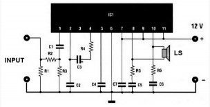
This 20w car audio amplifier circuit described hereoffers a20 wattboosterthatwillallow youtorealize thepower amplifierwith which one canincrease the poweroutputfromthe carstereoup to20Wattsmaximum.
The inputINis connected to theoutputof thereceiver,Uoutputis connectedto the speakeras shownoncaraudioamplifierscheme. It is veryimportanttoensurethat thespeakerhas no connection tothe chassis(ground)ifnot,the integrated circuitIC1,aTDA2004will soon bedamaged. Formounting,carefully followthe implementationof the caraudio amplifier scheme for thecomponents.The power supplywillkeep with 12volts.
(View)
View full Circuit Diagram | Comments | Reading(4947)
40W audio amplifier based on TDA1514
Published:2013/3/12 1:23:00 Author:Ecco | Keyword: 40W , audio amplifier
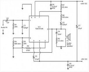
Many electronic audio amplifier circuit has been published here. This time, we use the TDA 1514 high performance hi-fi amplifier from Philips.The IC has many useful features such as thermal protection, Mute / stand-by facilities, low harmonic distortion, etc. This amplifier operates from dual power supply +25 / -25 V DC and can deliver output power of 40Watts into an 8 ohm speaker.
Amplifiedaudiosignalisis given topin1 ofThe ICand thecapacitorC2acts as a DC-coupling.ResistorsR3andR4determine theclosed loop gainandcan varybetween 20and 64dB.ResistorR2andcapacitorC4providesthecorrectimpedancespeaker Zobelnetworkandimprovefrequency response. ResistorsR7, R6and capacitorC5are bootstrapcomponents. Ifthebootstrappingis not requiredthenthese componentscan beremovedandPIN7 can be connected topin6,butpoweroutput will bereduced by about10%.R1isthe input resistanceandbiasthathas an effect oninputimpedance.
(View)
View full Circuit Diagram | Comments | Reading(1655)
10W Amplifier for portable cd players
Published:2013/3/12 1:19:00 Author:Ecco | Keyword: 10W Amplifier , portable cd players
This 10W Amplifier is ideal to drive medium size speakers and use it for a portable CD player or mp3 player. With only one active component of TDA2003 integrated circuit and a single supply source of 8 to 18 volts, this amplifier circuit can provide up to 10W of power to the load which can be between 2 and 8 ohm.
(View)
View full Circuit Diagram | Comments | Reading(1758)
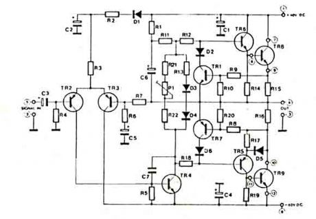
90 W audio power amplifier based on transistor
Published:2013/3/12 1:15:00 Author:Ecco | Keyword: 90 W, audio power amplifier, transistor
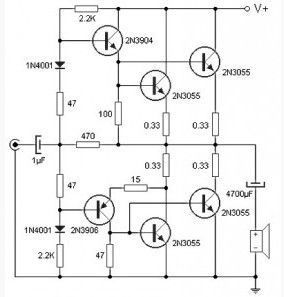
Using only four transistors in the quasi-complementary amplifier configuration, thistransistor power amplifier circuit can deliver 90W of power into 4 ohm loads and at low cost.
As shown in the transistor power amplifier circuit there are no expensive components in this circuit, except the power transformers and speakers. As shown in the diagram there are no expensive components in this circuit, except the power transformers and speakers. Input stage is formed by this two current driver directly raised a pair of transistors of the output stage. Transistor level end (2N3055) mounted on a heat sink to keep the lifetime of these devices. Supported by one source (of 80Vcc) at the output of the final stage, before the speaker, a capacitor is placed to block DC current, and just skip the audio signal. The power supply circuit 90 W audio power amplifier must be sufficient to provide current 1.5A per channel audio. Thus the power required to operate the stereo 3A and 6A is required for the four audio channels.
(View)
View full Circuit Diagram | Comments | Reading(12187)
100W Audio Amplifier with Integrated Circuit
Published:2013/3/12 1:13:00 Author:Ecco | Keyword: 100W , Audio Amplifier, Integrated Circuit
Almost all of the audio power amplifier if using integrated circuit amplifier as circuit shown here which is use M12CLK is an power operational amplifier. It allows an output stage operating at even 2 ohms impedance and gain power 150W. For stability and safety this system decided to make it work with 4 ohm speakers so we gain 100W RMS power.
(View)
View full Circuit Diagram | Comments | Reading(1941)
10 W Audio Amplifier based TDA 2003
Published:2013/3/12 0:55:00 Author:Ecco | Keyword: 10 W, Audio Amplifier
With only one active integrated circuit TDA 2003 as component this circuit can provide up to 10W of audio power to the load which can be between 2 and 8 ohm.
(View)
View full Circuit Diagram | Comments | Reading(2095)
High quality 10W Audio Amplifier
Published:2013/3/12 0:54:00 Author:Ecco | Keyword: High quality, 10W , Audio Amplifier
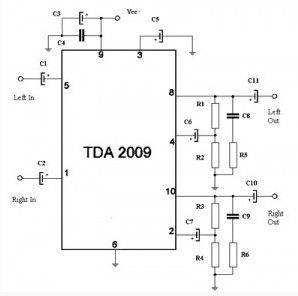
The main components of this high quality 10W stereo power amplifier circuit is uses TDA 2009 which is a class AB Audio Power Amplifier. IC TDA 2009 is specifically designed for high quality stereo applications such as HI-FI and music center.
As you can see on the circuit, this class AB amplifier IC requires only a few external components. And this 10 W audio amplifier circuit is also very easy to build. This 10W stereo amplifier circuit requires a stable power supply with a voltage of 18 V and 1A current needs.
(View)
View full Circuit Diagram | Comments | Reading(2002)
100 W valve audio amplifier
Published:2013/3/12 0:53:00 Author:Ecco | Keyword: 100 W , valve, audio amplifier
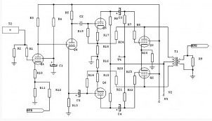
This is a valve audio amplifier circuit which can provide power up to 100W.
(View)
View full Circuit Diagram | Comments | Reading(1970)
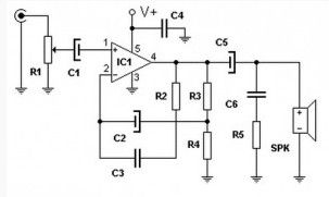
Audio Power amplifier (30W)
Published:2013/3/11 21:03:00 Author:Ecco | Keyword: Audio Power amplifier , 30W
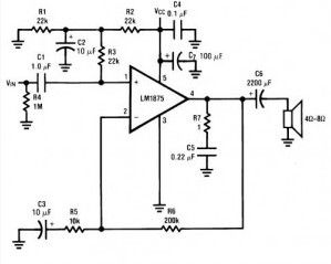
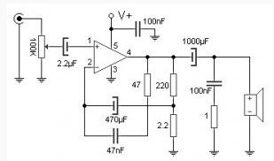
The following circuit uses LM1875 audio amplifier capable of delivering up to 30W RMS power into 8 ohm speakers with a total harmonic distortion (THD) 1%.
(View)
View full Circuit Diagram | Comments | Reading(2265)
12W FET audio amplifier
Published:2013/3/11 21:02:00 Author:Ecco | Keyword: 12W , FET, audio amplifier
This is a small 12W power amplifier on a load of 8 Ω, that combining the NE5534 integrated technology with transistors as V-MOSFET output stage get an excellent sound quality. The input sensitivity is 3V rms maximum, the distortion factor is 0.002% at 1 kHz, and frequency response is 15 Hz to 100 kHz. (-3dB).
(View)
View full Circuit Diagram | Comments | Reading(3400)
75W Transistor Audio Amplifier
Published:2013/3/11 21:00:00 Author:Ecco | Keyword: 75W , Transistor, Audio Amplifier
It is simple to build an amplifier, using the standard and stable and reliable. The 75 W amplifier circuit presented here is capable of driving 4 ohm, but, although used in 4 ohms, this amplifier has very few errors.
To be aware that there are no short-circuit output, so that when the speaker short, while the amplifier is working (with signal), there is a very real danger that may damage the transistor.
(View)
View full Circuit Diagram | Comments | Reading(6012)
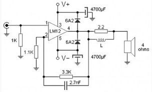
100 W audio amplifier based LM12CLK
Published:2013/3/11 20:59:00 Author:Ecco | Keyword: 100 W , audio amplifier
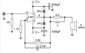
The 100W audio power amplifier is powered by the integrated circuit LM12CLK which is operational power amplifier. The monolithic IC can deliver 80W of sine wave power into 4Ω load with 0.01% distortion. Power bandwidth is 60 kHz .. Important features of IC LM12CLK include : controlled turn on, overvoltage shutdown, output-current limiting, dynamic safe-area protection, thermal limit, Input protection
This amplifier allows to operate at 2 Ω output impedance and gain 150W of power. For savety and system stability, this 100W audio amplifier is designed to work with 4-Ω speaker to gain the power of the 100W RMS.
(View)
View full Circuit Diagram | Comments | Reading(1957)
Low Power 6U8A Vacuum Tube Audio Amp
Published:2013/3/10 22:11:00 Author:Ecco | Keyword: Low Power, Vacuum Tube, Audio Amp
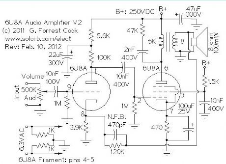
The line-level audio signal is sent through a 100K audio volume control and into the grid of the 6U8A triode section. The triode is wired as a standard class-A tube amplifier. The B+ line to the triode is isolated from the final amplifier's B+ through a 5.5K/22uF low pass filter, this prevents interstage feedback and oscillation.
The output of the triode amp is sent to the control grid of the 6U8A pentode section through a 10nF capacitor. The pentode is wired as a class-A amplifier with a transformer output. A negative feedback loop linearizes the amplifier's frequency response, this consists of a 120K resistor and 470pF capacitor from the speaker side of the output transformer to the cathode of the 6U8A triode. Feedback is kept to a fairly light level to preserve the amp's dynamics. The R/C network across the output transformer primary was adjusted for a flat frequency response. The pentode's screen grid is pulled up to the B+ voltage through a 1.5K current limiting resistor and AC-bypassed with a 10nF capacitor.
If a tone control is desired, it can be built onto the feedback loop, see my Squirrel Monkey amp project for an example of this type of tone control. If you build the amplfier and it oscillates, swap the output leads on the output transformer to correctly phase the feedback signal.
The power supply is not shown, this amp is designed to be an audio module that can be combined with other modules to build a radio or other audio devices. Any standard vacuum tube power supply should work here, it just needs to provide 6.3VAC for the filament and 250VDC for the B+ circuit. The amp should work fine with B+ values between 150VDC and 300VDC. Again, see my Squirrel Monkey amplifier for a power supply that will work with this amplifier.
(View)
View full Circuit Diagram | Comments | Reading(4067)
LM386 audio power amplifier and its pin main features
Published:2012/12/28 0:36:00 Author:Ecco | Keyword: audio power amplifier, pin main features
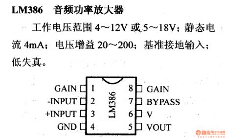
Operating voltage range is 4 ~ 12V or 5 ~~ 18V; quiescent current is 4mA; voltage gain is 20 to 200; reference ground input; low distortion.
(View)
View full Circuit Diagram | Comments | Reading(1813)
LM388 audio amplifier and its pin main characteristics
Published:2012/12/27 0:12:00 Author:Ecco | Keyword: audio amplifier, pin main characteristics
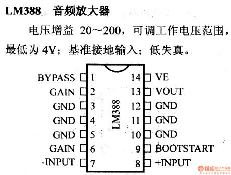
20 to 200 Voltage gain, adjustable operating voltage range,and its lowest bit is 4V; benchmark grounded input; low distortion.
(View)
View full Circuit Diagram | Comments | Reading(1872)
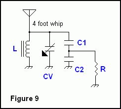
Tuning a Whip To Other Frequencies
Published:2012/12/12 21:11:00 Author:muriel | Keyword: Tuning, Whip, Other Frequencies
View full Circuit Diagram | Comments | Reading(748)
The audio amplifier circuit
Published:2012/11/29 21:19:00 Author:Ecco | Keyword: audio amplifier
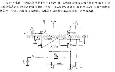
When the input signal level is less than 20mW , LM378 op amp directly uses 5Ω resistor to provide up to approximately 100mA peak current for load. When it is greater than 20mW, the load current bias flowing through 5Ω resistor to boost transistor and make it get conduction and increase the output power. Transistor and operational amplifier must be connected to a suitable heat sink.
(View)
View full Circuit Diagram | Comments | Reading(1588)
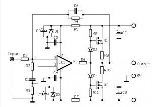
40 Watt Audio power Amplifier LM3876
Published:2012/9/12 20:55:00 Author:Ecco | Keyword: 40 Watt, Audio power Amplifier

This Circuit is based on the LM3876. A 11-pin plastic package IC with high performance audio power amplifier, an output mute function which can be used to eliminate switch-on and switch-off thumps to the loudspeaker load. It is capable of delivering 40W continuously into 8ohm load, and is fully protected using established techniques. The output stage is protected against short circuit to ground or either supply rail. Protection against transients from inductive loads is also provided at the output stage via internal clamp diodes.
Source: NEXT.GR (View)
View full Circuit Diagram | Comments | Reading(2681)
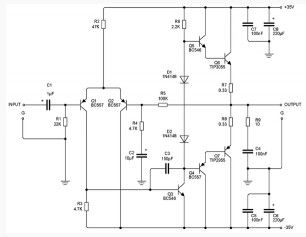
HI-FI Audio Amplifier 60W
Published:2012/9/12 20:48:00 Author:Ecco | Keyword: HI-FI Audio Amplifier, 60W
This amplifier has a high quality circuit that includes full sort circuit protection and very low T.H.D. at full range of frequency. It needs simmetrical power supply +-40V. The power transistors at the output are connected as DARLINGTON and both needs heatsinks. The power can reach 60 watts at 8 ohms or 80 Watts at 4 ohms. (View)
View full Circuit Diagram | Comments | Reading(3354)
PC audio amplifier 12Watt
Published:2012/9/12 20:45:00 Author:Ecco | Keyword: PC, audio amplifier, 12Watt
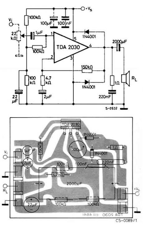
The circuit uses the TDA2030 which is a monolithic integrated circuit in Pentawatt? package, intended for use as a low frequency class AB amplifier. Typically it provides 14W output power (d = 0.5%) at 14V/4??; at ± 14V or 28V, the guaranteed output power is 12W on a 4?? load and 8W on a 8?? (DIN45500). The TDA2030 provides high output current and has very low harmonic and cross-over distortion. (View)
View full Circuit Diagram | Comments | Reading(2131)
| Pages:3/13 12345678910111213 |
Circuit Categories
power supply circuit
Amplifier Circuit
Basic Circuit
LED and Light Circuit
Sensor Circuit
Signal Processing
Electrical Equipment Circuit
Control Circuit
Remote Control Circuit
A/D-D/A Converter Circuit
Audio Circuit
Measuring and Test Circuit
Communication Circuit
Computer-Related Circuit
555 Circuit
Automotive Circuit
Repairing Circuit