
Index 58
TRANSDUCER_SCANNER
Published:2009/7/23 23:28:00 Author:Jessie
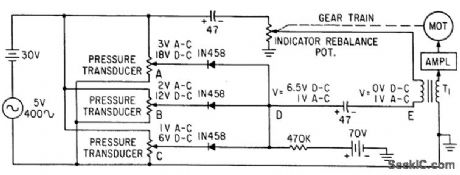
Monitors transducer outputs in parallel mode and reports when any one of measured parameters exceeds or falls below predetermined limit. Superimposing ac signal on d-c control voltage permits use of a-c servo as indicator.-S. Thaler, Solid. State Parallel-Mode Stunner Reads System Physical Parameters, Electronics, 34:19, p 78-80. (View)
View full Circuit Diagram | Comments | Reading(748)
Low_cost_two_chip_AM_radio_system
Published:2009/7/23 23:28:00 Author:Jessie


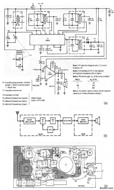
This AM radio requires only two ICs and few discrete components. A block diagram of the radio is shown in Fig. 2-63B. The typical PC-board layout is shown in Fig. 2-63C. The mixer-oscillator, two IF stages, and AGC section are contained within the LM3820. The power output of 0.25-W into an 8-Ω speaker is obtained in the LM386. (View)
View full Circuit Diagram | Comments | Reading(1514)
DIRECT_COUPLED_PREAMP
Published:2009/7/23 23:52:00 Author:Jessie

Direct-coupled silicon-transistor ampli0et uses zener diode to provide constant voltage, and has adequate d-c stability even with transistors having beta range of 3:1.-A. N. Desautels, Servo Preamplifiers Using Direct-Coupled Transistors, Electronics, 32:20, p 74. (View)
View full Circuit Diagram | Comments | Reading(0)
LOW_POWER_DRIVER
Published:2009/7/23 23:34:00 Author:Jessie
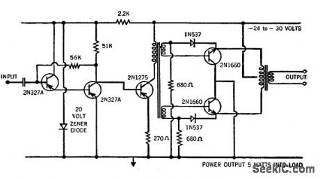
Pair of high-voltage, high-gain silicon power transistors gives 5W output from -55 to +125℃ when driven by 250-mw 2N1275 transistor.-New High Volt-age, High Gain Transistors (Raytheon Ad), Electronics, 33:35, p 42. (View)
View full Circuit Diagram | Comments | Reading(791)
Basic_function_test
Published:2009/7/23 23:51:00 Author:Jessie
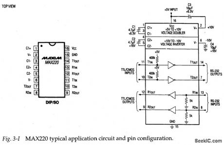
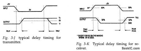
Figure 3-I shows the bypical application circuit and pin configuration for the MAX220.This EIA-232D interface(driver/receiver) operates from 5V,and is also suited for use in systems designed to V.28/V.24 specifications. The basic function is tested by comparing waveforms at the input and output of all four channels. In theory, the waveforms should be identical, except for possible delay. Figures 3-J and 3-K show typical delay timing for both the transmitter and receiver. For reference, the MAX220 receiver delay is 0.6μs (typical) and 3μs (maximum). The trans-mitter delay is 4μs (typical) and 10μs (maximum).
If one or more (but not all) of the four channels shows no output, severe dis-tortion, or excessive delay, the IC is suspect. If all four channels are defective, and +5 V is at pin 16, check the four capadtors (C1 through C4). These capadtors are used in the voltage-doubling (charge pump) and voltage-inverting functions within the IC. If the capacitors are good, and +5-V power is applied, but any or all of the channels are defective, suspqct the IC. (View)
View full Circuit Diagram | Comments | Reading(1103)
COMMON_PLATE_TRIODE_MIXER
Published:2009/7/23 23:34:00 Author:Jessie

Has two inputs, for combining mixed markers and radar video. Cathode resistors are unby-passed, for gain stabilization.-NBS, Handbook Preferred Circuits Navy Aeronautical Electronic Equipment, Vol. 1, Electron Tube Circuits, 1963, p N4-3. (View)
View full Circuit Diagram | Comments | Reading(676)
50_60_and_400_CPS_SERVO_AMPLIFIER
Published:2009/7/23 23:51:00 Author:Jessie
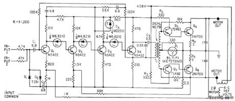
Solid-state 10-W amplifier handles all three power frequencies, operates from 28 V d-c, and uses four-transistor Darlington output stages to drive two-phase servo motor. Preamplifier and drive stages Q1-Q4 are all d-c coupled through zener diodes, with d-c feedback around all four stages to stabilize bias against temperature changes.-M. Bodnar, Versatile Servo Amplifier for 50, 60 or 400-Cycle Operation, Electronics, 36:3, p 44-45. (View)
View full Circuit Diagram | Comments | Reading(1603)
6_WAlT_SERVO_AMPLIFIER
Published:2009/7/23 23:50:00 Author:Jessie
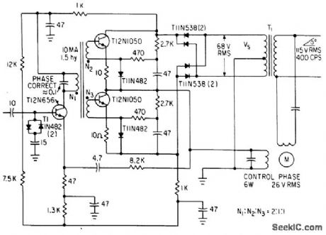
Unconventional output stage eliminates need for center tap on servomotor for controlled winding, gives 55% overall efficiency.-J. A. Walston and J. E. Setliff, Designing Servo Amplifiers for High Efficiency, Electronics, 36;6, p 62-63. (View)
View full Circuit Diagram | Comments | Reading(751)
Line_isolation
Published:2009/7/23 23:48:00 Author:Jessie
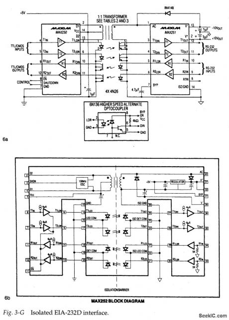
In telecom systems, the service provider incorporates line isolation to protect the network against unorthodox connections made by users. At the other end of the line, EIA-232D connections used in medical patient-monitoring equipment, data loggers, and supervisory computers (to name a few devices) must be isolated to protect the equipment from hardware failures. Isolation not only provides safety, but it can improve system performance.
As an example, EIA-232D links between a computer in one building and terminals in another building can show ground-current noise if the building earth-ground connections are at different potentials (as is usually the case). Isolation with a rating of 100 V can solve this problem. In severe industrial environments, a full UL-listed isolation barrier of 1500 V (or more) might be required.
The transmission of digital data, while maintaining an electrical barrier, usually involves transformers and opto-isolators, as shown in 6a of Fig. 3-G. The transformer supplies power to the other side of the barrier, and the opto-couplers handle data transmission across the barrier. However, there is a problem with this approach. The LEDs in opto-isolators (especially high-speed opto-isolators) require more current than normal logic circuits can provide. As a result, you must connect the outputs in parallel or add buffer ICs to get adequate drive current. Also, the isolated power supply must be fairly large because standard EIA-232D chips require a supply voltage of ±12V, as well as +5 V.
One approach to solving these power and data-transfer problems is to use matching interface chip sets, such as the MAX250/MAX251, shown in 6a of Fig. 3-G. These two ICs include circuitry for two EIA-232D transmitters and two receivers, circuitry for generating isolated power-supply voltage from the main (non-isolated) +5-V supply, and interface circuitry for driving and receiving signals from the external opto-isolators. You only need to supply the isolators, a 1:1 transformer, and a few passive components to complete an isolated dual-transceiver EIA-232D port. (Such circuits are covered in this chapter)
The alternate approach is to use a single-chip interface, such as the MAX252 shown in 6b of Fig. 3-G. This IC includes all of the circuitry in a standard 40-pin DIP, but provides the full UL-recognized 1500-V isolation barrier. (This approach is also covered in this chapter.) (View)
View full Circuit Diagram | Comments | Reading(1294)
THERMISTOR_CONTROL
Published:2009/7/23 23:48:00 Author:Jessie

Thermistors RT1 and RT2 in series are heated equally under no signal. Applying ac signal increases resistance of one and lowers that of other, depending on phase. Q1 and Q2 form ac preamp. Q3 and Q4 operate in switched mode as demodulator. Circuit can be used in place of mechanical servo.-I. C. Hutcheon, Using Thermistors as Servo Elements, Electronics, 34:5, p 52-55. (View)
View full Circuit Diagram | Comments | Reading(750)
PROGRAMMED_SERVO
Published:2009/7/23 23:38:00 Author:Jessie
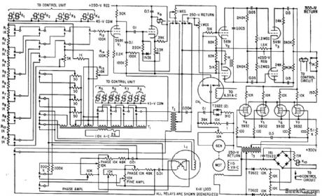
Positions printed-circuit board in response to controller commands. Component selection and insertion are also directed by controller. Relays apply fine and coarse voltages to servo positioner as required.-S. B. Korin and F. B. Spencer, Programmed Servo Speeds Short-Run production, Electronics, 32:10, p 54-56. (View)
View full Circuit Diagram | Comments | Reading(758)
35_W_CLASS_B_SERVO_AMPIIFIER
Published:2009/7/23 23:36:00 Author:Jessie
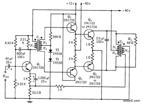
Gives power gain of 45 db. Voltage amplification is constant within 1.5 db of 36.5 db. Transformer data is for 400-cps operation.-Texas Instruments Inc., Transistor Circuit Design, McGraw-Hill, N.Y., 1963, p 244. (View)
View full Circuit Diagram | Comments | Reading(785)
15_W_CLASS_B_SERVO_AMPLIFIER
Published:2009/7/23 23:36:00 Author:Jessie
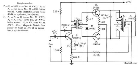
Gives power gain of 38 db. Voltage amplification is constant within 1.5 db of 40.5 db. Transformer data is for 400-cps operation.-Texas Instruments Inc., Transistor Circuit Design, McGraw-Hill, N.Y., 1963, p 240. (View)
View full Circuit Diagram | Comments | Reading(828)
SERVO_CONTROLLED_GAIN
Published:2009/7/23 23:34:00 Author:Jessie
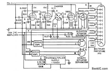
Gain is controlled by varying photomultiplier input volt-ager permitting photoelectric system to track brightness range from remote stars to moon.-W. J. Wichman and M. M. Birnbaum, Servo System Design for Balloon-Borne Star Trackers, Electronics, 34:35, p 43-46. (View)
View full Circuit Diagram | Comments | Reading(741)
BOOTSTRAPPED_EMITTER_FOLLOWER
Published:2009/7/23 23:41:00 Author:Jessie
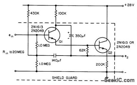
Band-width is 1 cps to 5 kc. Gives stable operation in servo systems even with positive feed.back, because loop gain is less than unity.- Transistor Manual, Seventh Edition, General Electric Co., 1964, p 217. (View)
View full Circuit Diagram | Comments | Reading(952)
400_CPS_SERVO_AMPLIFIER_SUPPRESSES_THIRD_HARMONIC
Published:2009/7/23 23:39:00 Author:Jessie
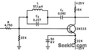
Single-transistor operational amplifier for 400aps servosystems gives accurate 90-deg phase shift at carrier frequency and open-loop gain of 34 db. Circuit resonance at 1,200 cps keeps third harmonic 20 db down.-M. Schmidt, Operational Amplifier Suppresses Third Harmonic, Electronics, 35:13, p 74. (View)
View full Circuit Diagram | Comments | Reading(697)
COMBINED_NEGATIVE_POSITIVE_FEEDBACK
Published:2009/7/23 23:39:00 Author:Jessie
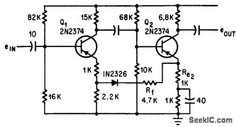
Two-stage common-emitter amplifier permits use of positive feedback to Rf along with negative feedback, to give stability factor of 5 and overall gain of 47 db with input impedance of 10,000 ohms for small-pulse amp lification in servo system.-N. A. Wade, Combined Feedback Stabilizes Amplifier, Electronics, 37:15, p 76. (View)
View full Circuit Diagram | Comments | Reading(2367)
COMPLEME_NTARY_TRANSISTOR_SERVO_AMPLIFIER
Published:2009/7/23 23:47:00 Author:Jessie

Use of direct coupling eliminates transformers. For d-c loads, C1 and C3 must be shorted. Will drive 20 V rms into 40-ohm load, giving 10 W. Voltage gain is 37 db and power gain is 60 db.-N. Freyling, High Performance All Solid-State Servo Amplifiers, Motorola Application Note AN-225, Jan. 1966 (View)
View full Circuit Diagram | Comments | Reading(933)
OPERATIONAL_PREAMPLIFIER
Published:2009/7/23 23:45:00 Author:Jessie
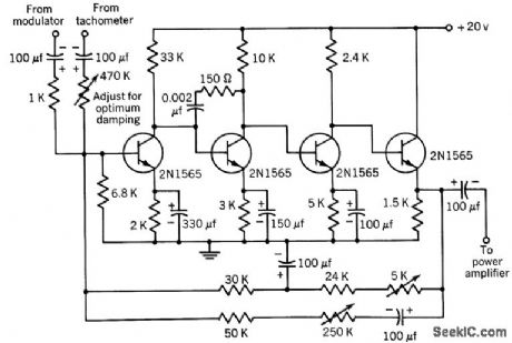
Used to sum modulator and tachometer outputs and provide signal for power amplifier that drives split-phase motor. Adjustable overall d-c feedback insures equal clipping when amplifier is overloaded, so squared output will have equal mark-space ratio.-Texas Instruments Inc., Transistor Circuit Design, McGraw-Hill, N.Y., 1963, p 493, (View)
View full Circuit Diagram | Comments | Reading(781)
PREFERRED_AMPLIFICATION_15_PREAMPLIFIER
Published:2009/7/23 23:44:00 Author:Jessie
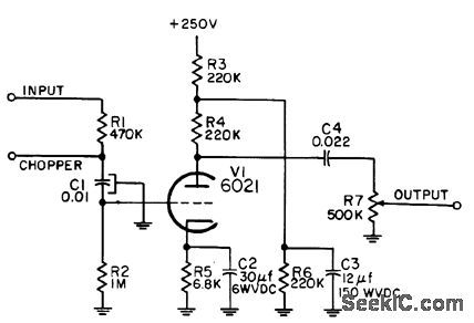
Used with instrument servo motor controller to increase available gain. Choice of pre-amplifier depends on error voltage per degree error available. Chopper is used with d-c inputs only.-NBS, Handbook Preferred Circuits Navy Aeronautical Electronic Equipment, Vol. I, Electron Tube Circuits, 1963, PC71,p 71-2. (View)
View full Circuit Diagram | Comments | Reading(664)
| Pages:58/126 At 204142434445464748495051525354555657585960Under 20 |
Circuit Categories
power supply circuit
Amplifier Circuit
Basic Circuit
LED and Light Circuit
Sensor Circuit
Signal Processing
Electrical Equipment Circuit
Control Circuit
Remote Control Circuit
A/D-D/A Converter Circuit
Audio Circuit
Measuring and Test Circuit
Communication Circuit
Computer-Related Circuit
555 Circuit
Automotive Circuit
Repairing Circuit