
Index 68
HARMONIC_DISTORTION_METER
Published:2009/6/30 2:27:00 Author:May
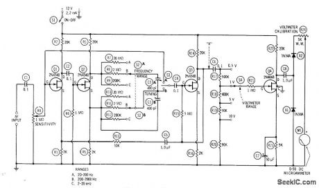
Used to measure total harmonic distortion of audio amplifier、component、or network.Pure sine-wavesignal is applied to devlee under test, and output of device is fed to AF input of distortion meter. After setting S2 to appropriate frequency range, close S1, set S3 at A, set S4 at appropriate voltage range, and adjust R1 for fullscale meter deflection. Record this voltage as E1. Set S3 to B, tune C3 for null, then set S4 to successively lower ranges for accurate reading of voltage at null. Record residual null voltage as E2. Percentage distortion is then 100E2/ E1.-R. P. Tumer, FET Circuits, Howard W.Sams, Indianapolis, IN, 1977, 2nd Ed., p 147-150. (View)
View full Circuit Diagram | Comments | Reading(3095)
FLUITER_METER
Published:2009/6/30 2:25:00 Author:May
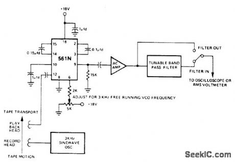
Signetics 561N PLL detects frequency variations in 3-kHz tone recorded on magnetic tape for test purposes. Frequency of VCO in 561N is set to nominal 3kHz with 5K pot.Demodulated output is AC coupled to amplffier having high input impedance. Either CRO or true PMS voltmeter can be used to make RMS flutter readings. To calibrate circuit, feed in 3-kHz tone from oscillator and measure output level shift when frequency is offset 1%.- Sig-netics Analog Data Manual, Signetics, Sunnyvale, CA 1977, p 860. (View)
View full Circuit Diagram | Comments | Reading(765)
ALARM_DETECTOR
Published:2009/6/30 1:38:00 Author:May
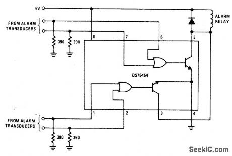
National DS75454 dual peripheral NOR driver operating from single 5-V supply energizes alarm relay when one of alarm transducers for either section delivers logic signal as result of intruder action.- Interface Databook, National Semiconductor, Santa Clara, CA, 1978, p 3-20-3-30. (View)
View full Circuit Diagram | Comments | Reading(657)
ALARM_SIGNAL_DETECTOR
Published:2009/6/30 1:37:00 Author:May
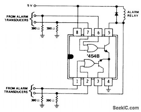
Texas Instruments SN75454B dual peripheral positive-NOR driver energizes alarm relay when alarm signal is received from any one of four different alarm transducers.- The Linear and Interface Circuits Data Book for Design Engineers, Texas Instruments, Dallas, TX, 1973, p 10-66. (View)
View full Circuit Diagram | Comments | Reading(771)
18_V_MONITOR
Published:2009/6/29 22:47:00 Author:May
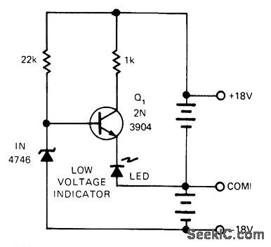
Circuit turns on LED when ±8 V battery pack discharges to predetermined low level, while drawing less than 1 mA when LED is off. Zener is reverse-biased for normal operating range of battery. When lower limit is reached, zener loses control and Q1 becomes forward-biased, turning on LED or other signal device to indicate need for replacement or recharging.-W. Denison and Y. Rich, Battery Monitor Is Efficient, yet Simple, EDN Magazine, Oct. 5, 1974, p 76. (View)
View full Circuit Diagram | Comments | Reading(887)
NICAD_MONITOR
Published:2009/6/29 22:40:00 Author:May
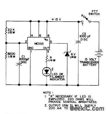
Uses two comparators, flip-flop, and power stage all in single NE555 IC. When battery voltage drops below 12-V threshold set by R1 and R2 for 15-V transceiver battery, one comparator sets flip-flop and makes output at pin 3 go high. IC then supplies up to 200 mA to LED or other indicator. For other battery voltage value, set firing point to about three-fourths of fully charged voltage. Sinqe battery voltage will show biggest drop when transmitting, connect monitor across transmit supply only so as to minimize battery drain.-A. Woemer, Ni-Cad Lifesaver, 73 Magazine, Nov. 1973, p 35-36. (View)
View full Circuit Diagram | Comments | Reading(892)
BATTERY_MONITOR
Published:2009/6/29 21:02:00 Author:May
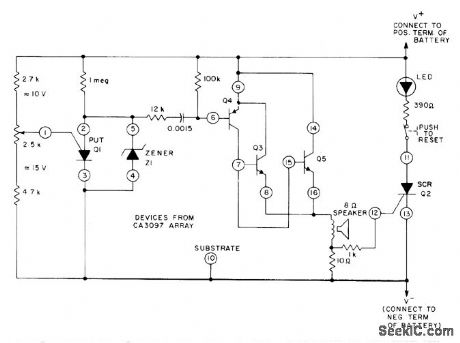
Uses CA3097 transistor array to provide active elements required for driving indicators serving as aural and visual warnings of low charge on nicad battery. LED remains on until circuit is reset with pushbutton switch.- Circuit Ideas for RCA Linear ICs, RCA Solid State Division, Somerville, NJ, 1977, p 9. (View)
View full Circuit Diagram | Comments | Reading(0)
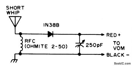
VOM_FIELD_STRENGTH_METER
Published:2009/6/29 4:26:00 Author:May
View full Circuit Diagram | Comments | Reading(708)
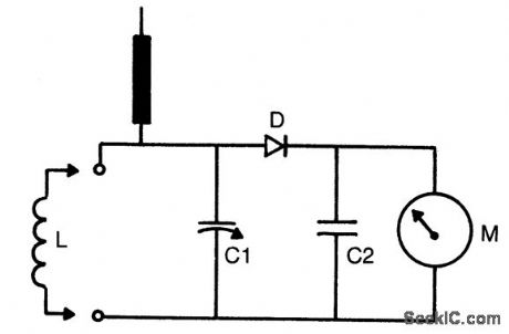
TUNED_FIELD_STRENGTH_METER
Published:2009/6/29 4:25:00 Author:May
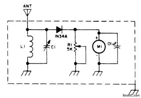
Circuit NotesResonant combination of L1 and C1 selected to cover frequencies desired. (View)
View full Circuit Diagram | Comments | Reading(726)
UNTUNED_FIELD_STRENGTH_METER
Published:2009/6/29 4:24:00 Author:May
Circuit Notes
Sensitivity is controlled by R1 and sen-sitivity of Meter M1. (View)
View full Circuit Diagram | Comments | Reading(679)
WASHER_TIMER
Published:2009/6/29 2:39:00 Author:May
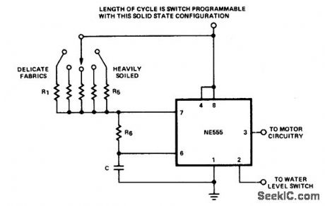
View full Circuit Diagram | Comments | Reading(701)
SIMPLE_FIELD_STRENGTH_METER
Published:2009/6/29 2:29:00 Author:May
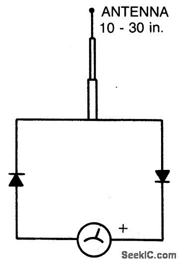


Circuit Notes
The circuit is frequency selective. It has been used from 2 meters through 160 meters. The telescoping antenna may be adjusted to its shortest length when working at 2 meters to keep the needle on the scale. Meter should be a 100 microamp to a 500 microamp movement. The diodes are germanium type, such as 1N34, etc. Silicon diodes will also work, but they are a bit less sensitive. (View)
View full Circuit Diagram | Comments | Reading(1962)
FIELD_STRENGTH_METER_15_to_150_MHz
Published:2009/6/29 2:28:00 Author:May
Circuit Notes
The tuning range is determined by coil (L) dimensions and setting of C1. Coils can be plugged in for multirange use or soldered in place if only limited frequency range is of interest. C1 = 36 pF variable, C2 =0047 disc, D = 1N60 (germanium) and M = 0-1 mA meter.For increased sensitivity, use 50μA meter. (View)
View full Circuit Diagram | Comments | Reading(640)
WINDOW_DETECTOR
Published:2009/6/29 2:25:00 Author:May
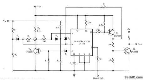


Uses one IC regulator to compare output voltages of two separate voltage dividers with fixed reference voltage. Resulting absolute error signal is amplified and converted to TTL-compatible Iogic signal. Voltage divider for lower limit of window detector is R1-R2 and for upper limit is R3-R4. Article covers circuit operation in detail.—N. Pritchard, Window Detector Uses 0ne IC Regulator, EDN Magazine, May 20, 1973, p 81 and 83. (View)
View full Circuit Diagram | Comments | Reading(0)
01_TO_90_SECOND_TIMER
Published:2009/6/29 2:25:00 Author:May
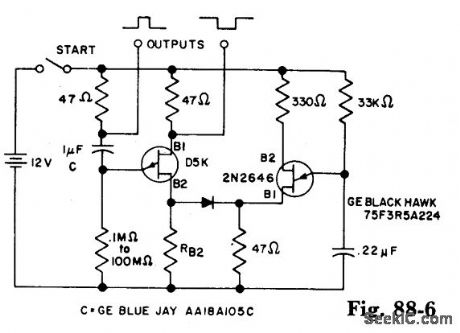
The timer interval starts when power is applied to circuit and terminates when voltage is applied to load. 2N2646 is used in oscillator which pulses base 2 of D5K. This reduces the effective L of D5K and allows a much larger timing resistor and smaller timing capacitor to be used than would otherwise be possible. (View)
View full Circuit Diagram | Comments | Reading(862)
ADJUSTABLE_SENSITIVITY_FIELD_STRENGTH_INDICATOR
Published:2009/6/29 2:24:00 Author:May
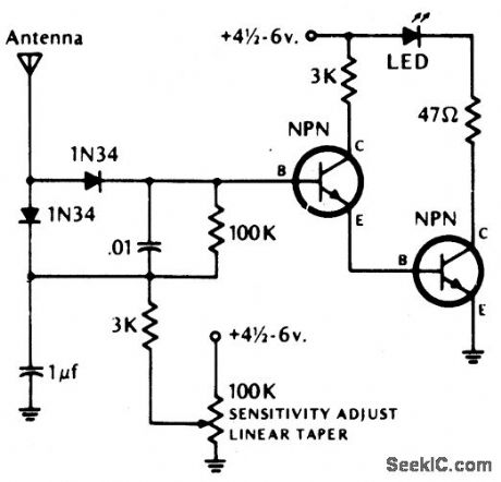
Circuit Notes
The LED lights if the rf field is higher than the pre-set field strength level. Diodes should be germanium. Transistors (NPN) = 2N2222, 2N3393, 2N3904 or equivalent. (View)
View full Circuit Diagram | Comments | Reading(3605)
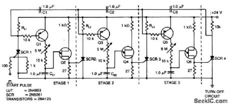
SEQUENTIAL_UJT_TIMER
Published:2009/6/29 2:22:00 Author:May
View full Circuit Diagram | Comments | Reading(635)
SEQUENTIAL_TIMER_1
Published:2009/6/29 2:21:00 Author:May
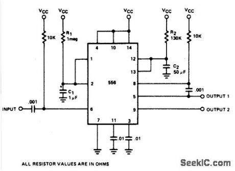
By utilizing both halves of a dual timer it is possible to obtain sequential timing. By connecting the output of the first half to the input of the second half via a.001μF coupling capacitor sequential timing may be obtained. Delay t1 is determined by the first half and t2 by the second half delay. The first halfof the timer is started by momentarily connecting pin 6 to ground. When it is turned out (determined by 1.1R1C1), the second half begins. Its duration is determined by 1.1R2C2. (View)
View full Circuit Diagram | Comments | Reading(1148)
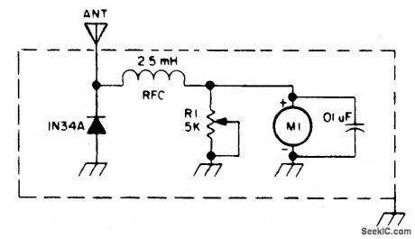
SENSITIVE_FIELD_STRENGTH_METER
Published:2009/6/29 2:18:00 Author:May
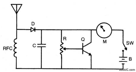
Circuit Notes
Increased sensitivity gives field strength reading from low power transmitters. Operat-ing range 3-30 MHz. To operate, adjust R for 1/3 to 1/2 scale reading. RFC = 2.5 mH choke, C =1.000 pF, R = 50 K pot, M = 0-1 mA, D = 1N34 or 1N60 (Germanium), Q = NPN (RCASK3020, 2N3904 or equivalent). (View)
View full Circuit Diagram | Comments | Reading(3)
LOW_COST_MICROWAVE_FIELD_STRENGTH_METER
Published:2009/6/29 2:13:00 Author:May
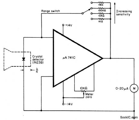
Circuit Notes
When operating, a waveguide directs energy onto a crystal detector. The diode I shown is for X-band operation. The waveguide is a 1 1/2 inch piece of plastic tubing with the ends flared. The plastic is coated with an electroless copper solution to provide a conducting surface. The dimensions are not critical. For calibrated readings, the meter is placed in a known field or else compared to a calibrated meter. To operate the meter, point it away from the signal. Switch the meter to the de-sired range, and adjust the zero control for a 0 reading. Then point the waveguide at the sig-nal, and read field strength directly. (View)
View full Circuit Diagram | Comments | Reading(729)
| Pages:68/101 At 206162636465666768697071727374757677787980Under 20 |
Circuit Categories
power supply circuit
Amplifier Circuit
Basic Circuit
LED and Light Circuit
Sensor Circuit
Signal Processing
Electrical Equipment Circuit
Control Circuit
Remote Control Circuit
A/D-D/A Converter Circuit
Audio Circuit
Measuring and Test Circuit
Communication Circuit
Computer-Related Circuit
555 Circuit
Automotive Circuit
Repairing Circuit