
Index 67
AIR_FLOW_DETECTOR
Published:2009/7/1 0:34:00 Author:May
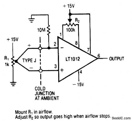
View full Circuit Diagram | Comments | Reading(0)
LASER_LIGHT_DETECTOR
Published:2009/6/30 23:30:00 Author:May
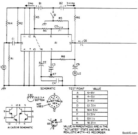

The laser light detector utilizes a sensitive photo transistor (Q5) placed at the focal point of a lens (LE2). The output of Q5 is fed to a sensitive amplifier consisting of array (A1) and is biased via the voltage divider consisting of R14 and R1. The base is not used.Q5 is capacitively coupled to a Darlington pair for impedance transforming and is further fed to a capacitively coupled cascaded pair of common-emitter amplifiers for further signal amplification. Sensitivity control (R7) controls base drive to the final transistor of the array and hence controls overall system sensitivity. Output of the amplifier array is capacitively coupled to a one-shot consisting of Q1 and 6|2 in turn integrating the output pulses of Q2 onto capacitor C8 through Dl. This dc level now drives relay drivers 6)3 and 6)4 activating K1 along with energizing indicator D3, consequently controlling the desired external circuitry. The contacts of K1 are in series with low ohm resistor R13 to prevent failure when switching capacitive loads. J2 allows listening to the intercepted light beam via headsets. This is especially useful when working with pulsed light sources such as GaAs lasers or any other varying periodic light source. (View)
View full Circuit Diagram | Comments | Reading(1293)
GRID_DIP_METER
Published:2009/6/30 23:13:00 Author:May

Uses ordinary No.48 or 49 pilot lamp as resonance indicator will oscillate ai frequencies up to 12 MHz.Wind L1 to cover desired frequency ranges.-Circuits,73 Magazine,April 1973,p 133. (View)
View full Circuit Diagram | Comments | Reading(2764)
POSITIVE_PEAK_DETECTOR
Published:2009/6/30 22:24:00 Author:May
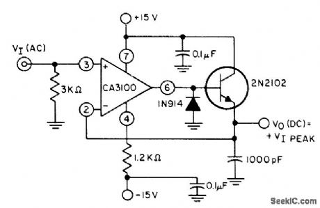
CA3100 bipolar MOS opamp is connected as wideband noninverting amplifierto provide essentiany constantgain for wide range of input frequendes,Diode clips negative half-cycles, so output of transistor is proportional only to positive input peaks.- Circuit Ideas for RCA Linear ICs, RCA Solid State Division, Somerville, NJ, 1977, p 16. (View)
View full Circuit Diagram | Comments | Reading(0)
AUDIBLE_S_METER
Published:2009/6/30 22:12:00 Author:May
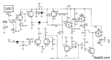
When connected to repeater circuit generates tone burst 3 s after input signal has dropped out, with duration of 60 ms. Pitch of tone varies inversely with signal strength; highest pitch of 3500 Hz thus represents weak signal, and 350-Hz pitch corresponds to strongest input signal. Can be used to check performance of transmitters and antennas using that repeater. Repeater receiver must havesmeter, as in RCA CA3089E receiver, output of which can be fed to terminal A of circuit. Switch changes output from S-meter to audible encoder. Input B goes to squelch, C goes to +12 V source that is on when receiver is on, and D provides tone output for feed to audio amplifier and loudspeaker. Unlabeled transistors can be any medium-gain small-signal NPN and PNP silicon, comparable to European BC107 and BC177.-F. Johnson, Audible S-Meter for Repeaters, Ham Radio, March 1977, p 49-51. (View)
View full Circuit Diagram | Comments | Reading(938)
PEAK_PROGRAM_METER_TESTER
Published:2009/6/30 22:09:00 Author:May
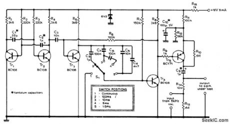
Used with 5-kHz audio oscillator to produce tone bursts of 1.5,5,10,and 100 ms,as required for checking response of program meter to tone bursts.Transistors Tr3 and Tr, form mono with switched timing capadtors. Article covers calibration and use.-E. T. Garthwaite, Tone Burst Generator for Testing P P.Ms, Wireless World, Aug. 1976, p 53. (View)
View full Circuit Diagram | Comments | Reading(1237)
AF_VOLTMETER
Published:2009/6/30 22:09:00 Author:May
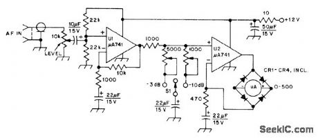
Although not calibrated on absolute basis, either 3 dB or 10 dB of attenuation can be switched in with S1 for measuring purposes. Internal ad justments are made easily by tacking 51-ohm resistor temporarily across input, then driving input with step attenuator fed with audio power at -10 dB by generator having 50-ohm pad in its output. CR1-CR4 are 1N914.-W Hayward, Defining and Measuring Receiver Dynamic Range, 057, July 1975, p 15- 21 and 43. (View)
View full Circuit Diagram | Comments | Reading(1043)
AUDIO_FREQUENCY_METER
Published:2009/6/30 21:32:00 Author:May
Covers 0-100 kHz in four ranges. Meter reading is indepen-dent of signal amplitude frorn 1.7 VRMS upward and independent of waveform over wide range.Linear response means only one point need be calibrated in each frequency range. Circuit uses two overdriven FET amplifier stages in cascade.Square-wave output of Iast stage is rectified by X1 and X2. Deflection of meter depends only on number of pulses per second passing through meter so is proportional to pulse frequency.Battery drain is 1.4 mA.-R. P. Tumer, FET Cir-cuits, Howard W. Sams, Indianapolis, IN, 1977, 2nd Ed., p 129-131. (View)
View full Circuit Diagram | Comments | Reading(0)
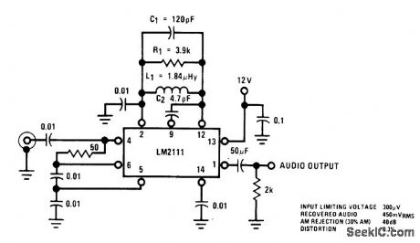
5_mA_S_METER
Published:2009/6/30 21:31:00 Author:May
Circuit designed for 5-mA meter movement uses two-stage voltage ampilfer Q1-Q2 with emitter-follower output Q3 serving as impedance-matching stage AF input for S-9 reading is 25-30mV P-P and forfull scale is 50-60mV P-P Frequency response is 500 Hz to 10 kHz-M,A,Chapma,Solid-State S-Me-ters,Ham Radio,March 1975 p 20-23 (View)
View full Circuit Diagram | Comments | Reading(1268)
LEVEL_DETECTOR
Published:2009/6/30 21:29:00 Author:May
Circuit lights green LED if signal at output of audio preamp exceeds 1V peak for predetermined period. Red LED comes on when tone-control stage at output of preamp is on verge of clipping. VU meter driver circuit is also provided. Entire circuit must be duplicated for other stereo channel. Article describes drcuit operation in detail and gives all associated circuits used in high-performance audio preamp. D1 is 1N914; red LED is TIL209 or equivalent; green LED is TIL211.-D. Self, Ad.vanced Preamplifier Design, Wireless World, Nov. 1976, p 41-46. (View)
View full Circuit Diagram | Comments | Reading(0)
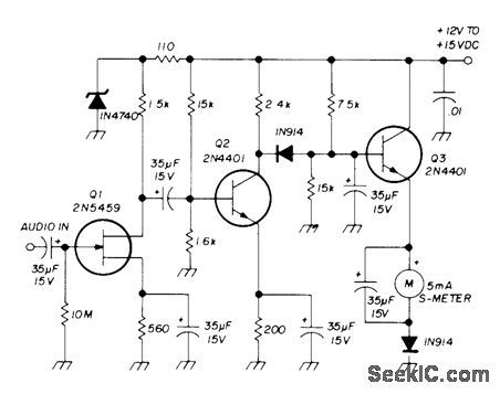
1_mA_S_METER
Published:2009/6/30 21:27:00 Author:May
Amplifier designed for 1-mA meter movement consists of two-stage voltage amplifier driving meter rectifier. FET input provides high impedance to detected audio and minimizes loading and distortion problems. Q2 is common-emitter voltage amplifier with simple positive-pulse rectifier for meter. GI filters rectified audio signal. AF input for S-9 reading is 25-30 mV P-P and for full scale is 50-60 mV P-P Frequency response is 500 Hz to 10 kHz.-M A. Chapman, Solid-State S-Meters, Ham Fladio, March 1975, p 20-23. (View)
View full Circuit Diagram | Comments | Reading(2611)
ADDING_S_METER
Published:2009/6/30 21:24:00 Author:May
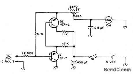
Circuit works well with most all-band receivors.Q1 may also be SK3011,NR5, TR-10,or DS75.Q2 may also beHE1,SK-3005, or TR-06. Value of 1.2-megohm input resistor may need to be adjusted depending on AVC voltage,to prevent strong signals from overloading meter.- Novice Q & A, 73 Magazine, Feb 1977,p 127. (View)
View full Circuit Diagram | Comments | Reading(999)
ADD_ON_S_METER
Published:2009/6/30 21:21:00 Author:May
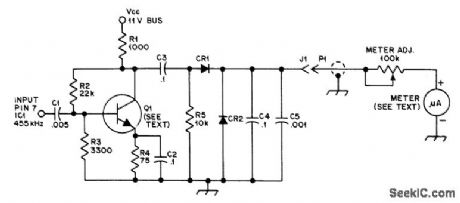
Although designed for use with Clegg FM-27B 2-meter FM receiver, circuit can be readily adapted to other receivers. Am-plifier brings low-level455-MHz IF signal up to level suitable for driving meter. For other IF, such as 10.7 or 11.7 MHz, capacitor values should be changed accordingly. Any NPN tran, sistor with beta of 30 or more at IF value can be used. Diodes can be any type. Supply should be regulated but can be 7-14 V. Output of diode detector will vary from 0 to 1 V at nominal impedance of 20K; for best result, meter with 20- to 50-μA movement can be used.-M. Stern, FM-27B S-Meter, QST, Doc. 1976, p 35. (View)
View full Circuit Diagram | Comments | Reading(2673)
IC_DflIVE_FOB_VU_METER
Published:2009/6/30 21:17:00 Author:May
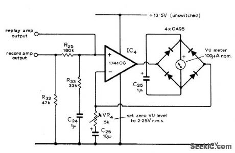
Used in high-quality stereo cassette deck operating from AC line or battery. Meter rectifier bridge is in feedback loop of opamp, to give highly linear AC/DC conversion with flat frequency/amplitude response and short voltage rise time at low cost. Article gives all other circuits of cassette deck and describes operation in detaiL-J. L. Linsley Hood, Low-Noise, Low-Cost Cassette Deck, Wireless World, Part 1-May 1976, p 36-40 (Part 2-June 1976, p 62-66; Part 3-Aug. 1976, p 55-56). (View)
View full Circuit Diagram | Comments | Reading(1002)
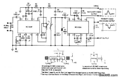
VIDEO_IF_AMPLIFIER_AND_LOW_LEVEL_VIDEO_DETECTOR_CIRCUIT_1
Published:2009/6/30 21:16:00 Author:May
View full Circuit Diagram | Comments | Reading(606)
19_V_BATTERY_OPERATEDIONIZATION_TYPE_SMOKEDETECTOR
Published:2009/6/30 3:49:00 Author:May
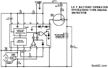
View full Circuit Diagram | Comments | Reading(596)
POWER_FAILURE_DETECTOR
Published:2009/6/30 3:15:00 Author:May
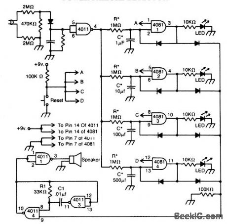
This circuit indicates that a power outage occured for with the values given for R* and C*. After a power failure, pushing the Reset button. (View)
View full Circuit Diagram | Comments | Reading(1148)
GROUND_TESTER
Published:2009/6/30 3:08:00 Author:May

This circuit checks the reliability of appliances so that the equipment may be used safely. The test circuit must be plugged into a properly wired three terminal wall outlet. When a two-lead or three-lead appliance is plugged into circuit outlet S01, neon lamps NE1 and NE2 will light if the appliance is safe. If neon NE2 is lit the appliance is dangerous, because the neutral lead is 110 Vac above ground. (View)
View full Circuit Diagram | Comments | Reading(1077)
LOW_COST_RING_COUNTER
Published:2009/6/30 2:47:00 Author:May
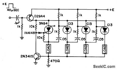
Circuit Notes
This ring counter makes an efficient, low cost circuit featuring automatic resetting via the first stage 3N84. As many stages as desired may be cascaded. (View)
View full Circuit Diagram | Comments | Reading(884)
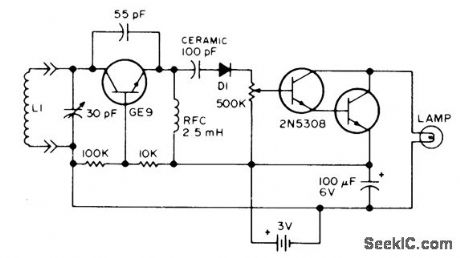
LIGHT_INTERRUPTION_DETECTOR
Published:2009/6/30 2:37:00 Author:May
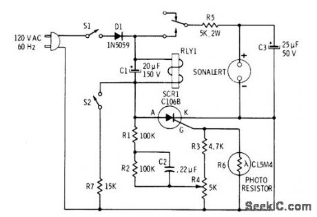
Use of SCR as regenerative amplifier rather than as switch gives extremely high sensitivity to very slight reductions in light reading photoresistor. Requires no light source or accurately aligned light-beam optics. In typical application as burglar alarm, light shining through window from streetlight provides sufficient ambient illumination so any movement of intruder within 10 feet of unitwill energize Sonalertalarm. Sensitivity control R4 is adjusted so SCR receives positive pulses from AC line, but their amplitude is not quite enough to start regenerative action of SCR. Reduction in light then increases resistance of photoresistor enough to raise level of gate pulses for SCR, starting regenerative amplification that energizes relay. Use Mallory SC-628P Sonalert which produces pulsed 2500-Hz sound. With S2 open, alarm stops when changes in light cease. With S2 closed, alarm is latched on and S1 must be opened to stop sound.-R. F. Graf and G. J. Whalen, The Build-It Book of Safety Electronics, Howard W. Sams, Indianapolis, IN, 1976, p 7-12. (View)
View full Circuit Diagram | Comments | Reading(0)
| Pages:67/101 At 206162636465666768697071727374757677787980Under 20 |
Circuit Categories
power supply circuit
Amplifier Circuit
Basic Circuit
LED and Light Circuit
Sensor Circuit
Signal Processing
Electrical Equipment Circuit
Control Circuit
Remote Control Circuit
A/D-D/A Converter Circuit
Audio Circuit
Measuring and Test Circuit
Communication Circuit
Computer-Related Circuit
555 Circuit
Automotive Circuit
Repairing Circuit