
Index 128
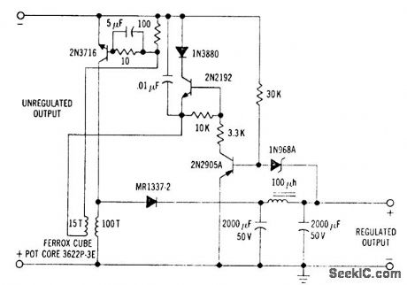
Duty_cycle_and_frequency_control_circuitry_for_a_switching_mode_regulator
Published:2009/7/20 21:08:00 Author:Jessie
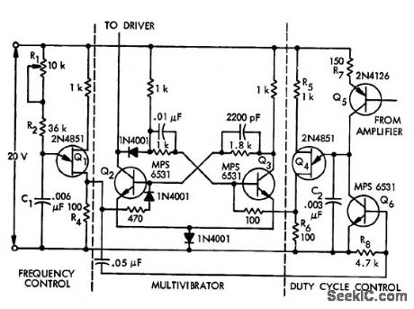
Duty cycle and frequency control circuitry for a switching mode regulator.Q1 sets the basic operating frequency of the regulator at 5 kHz, while Q4 controls the duty cycle (courtesy Motorola Semiconductor Products Inc.). (View)
View full Circuit Diagram | Comments | Reading(706)
Fixed_negative_voltage_regulator_using_the_μA79HG_which_can_supply_a_minimum_of_5_amperes_at_voltages_from__23_volts_to__24_volts_
Published:2009/7/20 21:06:00 Author:Jessie
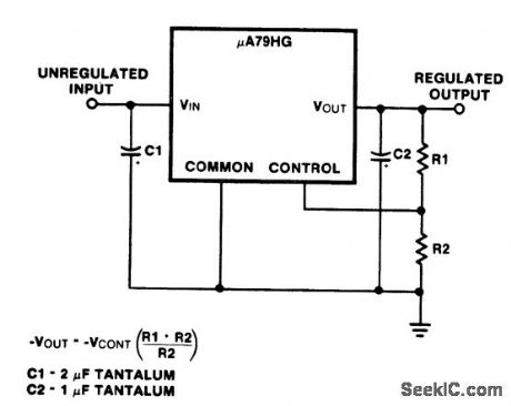
Fixed negative voltage regulator using the μA79HG, which can supply a minimum of 5 amperes at voltages from -2.3 volts to -24 volts (courtesy Fairchild Semiconductor). (View)
View full Circuit Diagram | Comments | Reading(576)
Negative_floating_regulator100_volts_using_an_ECG915_or_ECG915D_IC
Published:2009/7/20 21:22:00 Author:Jessie
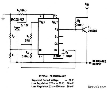
Negative floating regulator(100 volts) using an ECG915 or ECG915D IC.For a ±5% fixed output, H1 should be 3.57 ohms and R2 should be 97.6 ohms (courtesy GTE Sylvania Incorporated). (View)
View full Circuit Diagram | Comments | Reading(661)
TRUE_TWIN_TRIODE_CASCODE
Published:2009/7/20 21:22:00 Author:Jessie
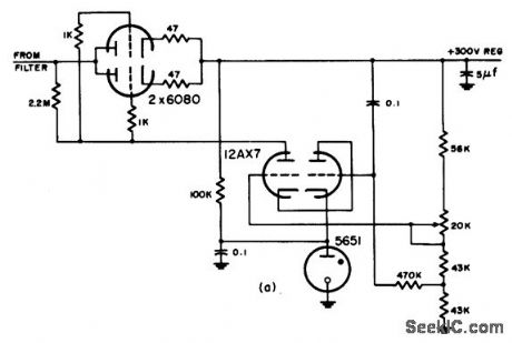
Use of 5-mfd capacitor across regulated output reduces adverse effect of 2.2-meg plate load resistor g frequency response. Cascade circuit is Used when required gain is too high for single triode because it avoids need for second d-c supply that would be required for screen if pentode were used.-NBS, Handbook Preferred Circuits Navy Aeronautical Electronic Equipment, Vol. 1 Electron lube Circuits, 1963, p N2-2. (View)
View full Circuit Diagram | Comments | Reading(888)
100_volt_RMS_regulator_using_a_triac_and_UJT
Published:2009/7/20 21:21:00 Author:Jessie
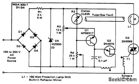
100-volt RMS regulator using a triac and UJT. To eliminate 60-hertz modulation of the photocell it is mounted at one end of a black tube with the other end directed at the back side of the lamp reflector. The reflector glows red and since it has a relatively large mass it cannot respond to the supply frequency. This provides a form of integration (courtesy Motorola Semiconductor Products Inc.). (View)
View full Circuit Diagram | Comments | Reading(1512)
MODIFIED_TWIN_TRIODE_CASCODE
Published:2009/7/20 21:21:00 Author:Jessie

Plate resistor for lower-potention triode parallels top triode, which is plate load for true cascode. This increases gain of circuit by increasing average plate current and thereby transcon-ductance of bottom triode.-NBS, Handbook Preferred Circuits Navy Aeronautical Electronic Equipment, Vol. 1, Electron Tube Circuits, 1963, p N2-2. (View)
View full Circuit Diagram | Comments | Reading(897)
INVERTED_OUTPUT_SWITCHING_REGULATOR
Published:2009/7/20 21:20:00 Author:Jessie
Simple 6-kc blocking oscillator circuit serves both for sensing and duty cycle control. Arrangement is more efficient than conventional series-pass regulators. Inverted polarity is added feature. Will regulate 20-v output within 1% overload range of 50 ma to 1 amp.-H. Weber, Two Unique Switching Voltage Regulators Using Blocking Oscillators, Motorola Application Note AN-163, Aug. 1965. (View)
View full Circuit Diagram | Comments | Reading(723)
20_watt_3_phase_inverter_with_12_volt_DC_input_and_115_volt_400_hertz_AC_output
Published:2009/7/20 21:17:00 Author:Jessie
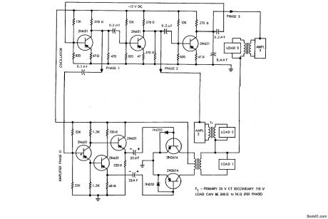
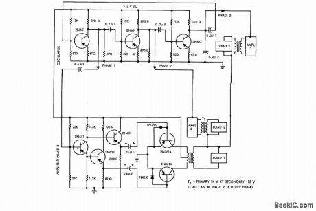
20-watt 3-phase inverter with 12-volt DC input and 115-volt 400-hertz AC output (courtesy Motorola Semiconductor Products Inc.). (View)
View full Circuit Diagram | Comments | Reading(5237)
BALANCED_OUTPUT_PENTODE_TWIN_TRIODE
Published:2009/7/20 21:39:00 Author:Jessie
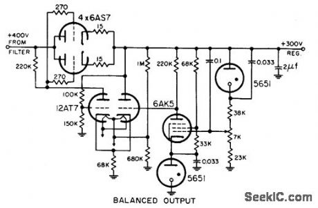
Arrangement gives high gain, approaching 10,000, along with more ripple reduction than is generally required.-NBS, Hand-book Preferred Circuits Navy Aeronautical Electronic Equipment, Vol. 1, Electron Tube Circuits, 1963, p N2-4. (View)
View full Circuit Diagram | Comments | Reading(735)
TWIN_TRIODE_CASCADE
Published:2009/7/20 21:37:00 Author:Jessie
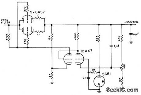
Has self-contained reference voltage, and does not load reference tube. Is theoretically capable of highest possible gain obtainable with single-envelope d-c amplifiers.-NBS, Handbook Preferred Circuits Navy Aeronautical Electronic Equipment, Vol. 1, Electron Tube Circuits, 1963, p N2-3. (View)
View full Circuit Diagram | Comments | Reading(727)
150_V_REGULATOR_WITH_EXTERNAL_REFER_ENCE
Published:2009/7/20 21:36:00 Author:Jessie
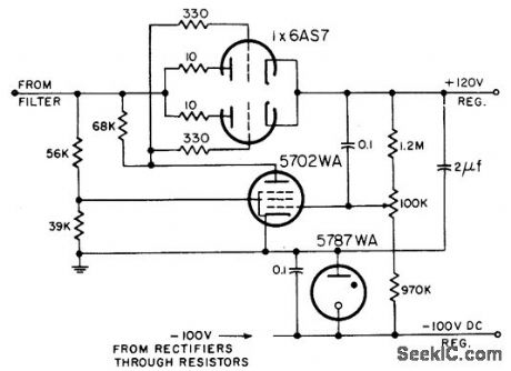
Permits wider supply voltage range and better operation thon arrangements using self-contained reference.-NBS, Hand. book Preferred Circuits Navy arrangements Electronic Equipment, Vol. 1, Electron Tube Circuits, 1963, p N2-4. (View)
View full Circuit Diagram | Comments | Reading(808)
Multi_output_low_voltage_power_supply_for_TEL_and_CMOS_
Published:2009/7/20 21:35:00 Author:Jessie
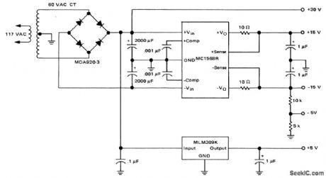
Multi output low-voltage power supply for TEL and CMOS (courtesy Motorola Semiconductor Products Inc.). (View)
View full Circuit Diagram | Comments | Reading(1886)
PENTODE_REGULATOP
Published:2009/7/20 21:35:00 Author:Jessie
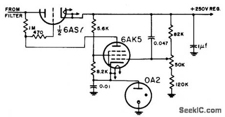
Reference lube is in cathode circuit of 6AK5, and plate load of pentode is high (1 meg), resulting in poor frequency response.-NBS, Handbook Preferred Circuits Navy Aeronautical Electronic Equipment, Vol. 1, Electron Tube Circuits, 1963, p N2-2. (View)
View full Circuit Diagram | Comments | Reading(935)
ZERO_IMPEDANCE_VOLTAGE_REGULATOR
Published:2009/7/20 21:34:00 Author:Jessie
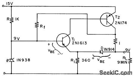
Uses two transistors and controlled positive feedback along with temperature compensation to reduce output resistance to zero while holding output voltage constant. Also gives some current overload protection. Values shown provide 1 amp at 9 v.-G. Duggan, Zero Impedance Voltage Regulator, EEE, 11:5, p 91-92. (View)
View full Circuit Diagram | Comments | Reading(731)
BASIC_SERIES_REGULATOR
Published:2009/7/20 21:28:00 Author:Jessie
Provides voltage regulation within 2% at 400 ma, with peak-to peak output ripple below 0.3 v. Output impedance is less than 2 ohms from d-c to 20 cps.- Transistor Manual, Seventh Edition, General Electric Co., 1964, p 227. (View)
View full Circuit Diagram | Comments | Reading(927)
RMS_voltage_regulator_using_an_SCR_and_a_PUT
Published:2009/7/20 21:28:00 Author:Jessie
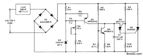
RMS voltage regulator using an SCR and a PUT.This circuit provides90 ±2 volts at 500 watts for an input of 110 to 130 volts RMS(courtesy Motorola Semiconductor Products Inc.). (View)
View full Circuit Diagram | Comments | Reading(4112)
14_KV_400_CPS_CRT_SUPPLY
Published:2009/7/20 21:26:00 Author:Jessie
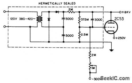
Used to power special-purpose dark-trace tube. Triode in parallel with output provides voltage regulation to overcome effects of changing line voltage, improve output ripple, and improve output impedance characteristics.-NBS, Handbook Preferred Circuits Navy Aeronautical Electronic Equipment, Vol. 1, Electron Tube Circuits, 1963, p N14-1. (View)
View full Circuit Diagram | Comments | Reading(631)
Line_operated_15_kHz_inverter_with_120_volt_output
Published:2009/7/20 21:26:00 Author:Jessie
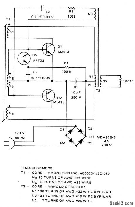
Line operated 15 kHz inverter with 120-volt output. This circuit can be used in ultrasonic applications and for high-frequency fluorescent lights. The output waveform is a 120-volt amplitude-modulated 15 kHz square wave (courtesy Motorola Semiconductor Products Inc.). (View)
View full Circuit Diagram | Comments | Reading(746)
BATTERY_VOLTAGE_REGULATOR
Published:2009/7/20 21:25:00 Author:Jessie
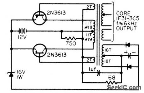
Used in battery-powered instruments to compensate for wide range of battery voltages. Converter serves to provide required variety of operating voltages and isolate equipment from sup ply. Will hold output within 0.5 v of 16 v for input range of 11.5 to 19 v.-C. D. Lind-say, Combined Battery Converter-Regulator Power Source, EEE, 14:3, p 61. (View)
View full Circuit Diagram | Comments | Reading(644)
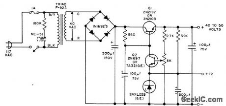
Dual_voltage_transmitter_power_supply_with_800_volt_and_450_volt_taps
Published:2009/7/20 21:25:00 Author:Jessie
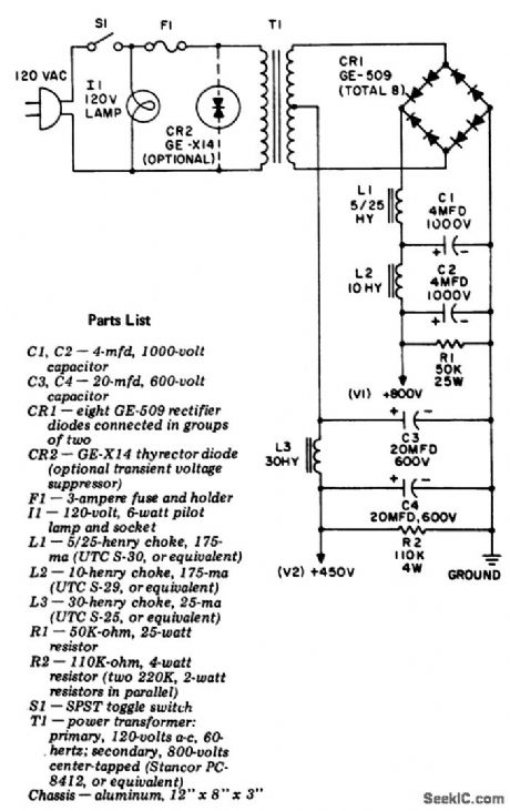
Dual-voltage transmitter power supply with 800-volt and 450-volt taps.This circuit Will handle a 100-watt transmitter,The 800-volt tap is rated at 175 mA intermittent duty with 1% ripple and 16% load rejection.The 450-volt tap is rated at 25 mA with 0.02% ripple. The voltage at V2 can be lowered to 375 volts by removing C3,The current rating of V2 can be Increased by selecting L3 with a higher current rating(courtesy General Electric Company). (View)
View full Circuit Diagram | Comments | Reading(734)
| Pages:128/291 At 20121122123124125126127128129130131132133134135136137138139140Under 20 |
Circuit Categories
power supply circuit
Amplifier Circuit
Basic Circuit
LED and Light Circuit
Sensor Circuit
Signal Processing
Electrical Equipment Circuit
Control Circuit
Remote Control Circuit
A/D-D/A Converter Circuit
Audio Circuit
Measuring and Test Circuit
Communication Circuit
Computer-Related Circuit
555 Circuit
Automotive Circuit
Repairing Circuit