
Noise Generator
Index
AUDIO FREQUENCY DIGITAL NOISE GENERATOR
Published:2012/9/9 20:56:00 Author:Ecco | Keyword: AUDIO FREQUENCY, DIGITAL , NOISE GENERATOR
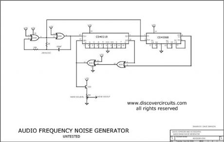
When you need to test an audio circuit with broadband noise, this circuit works great. It uses just three inexpensive C-MOS ICs that generate a series of output pulses whose widths vary randomly. I included a level control pot.
Source: discovercircuits (View)
View full Circuit Diagram | Comments | Reading(0)
Synchronized clock oscillator circuit diagram
Published:2012/7/8 21:23:00 Author:Ecco | Keyword: Synchronized clock oscillator
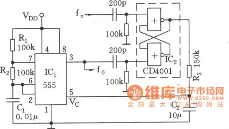
As shownin the figure, the controlled multivibrator iscomposed of 555 and R1, R2, C1, and the oscillation frequency is related to the RC time constant , but alsocan beadjustedby DC level of the control side. The DC level depends on the reference frequency f. After low-pass filter, the square wave is output by RS flip flop which is locked by oscillation frequency fo = Nfn output from 555. CD4001's two NOR gate circuits form the RS flip flop , when it is in a locked case , the duty cycle of the output will be kept, and thus the filtered DC level keepsconstant. If 555 oscillation frequency f0drift high(or fn reduces) , then the duty cycle will increase, thenthe DC control level will increase accordingly , frequency will decline; and vice versa.
(View)
View full Circuit Diagram | Comments | Reading(1727)
Small electronic coupling oscillator circuit diagram
Published:2011/12/8 20:23:00 Author:Ecco | Keyword: Small , electronic coupling oscillator
View full Circuit Diagram | Comments | Reading(1032)
RESISTANCE_CONTROLLED_OSCILLATOR
Published:2009/7/19 22:00:00 Author:Jessie
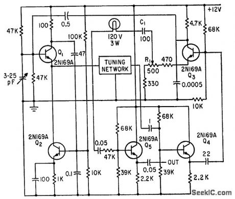
Both positive and negative feedback loops ore used, with notch network as frequency-determining element. Incandescent lamp in forward loop give amplitude stabilization. Tuning network contains resistance-to-frequency tranducers.-V. C. Vanderbilt and C. L. Zimmer, Magnetic Tape Recorder Programs Engine Dynamometer Tests, Electronics, 33:51, p 74-77. (View)
View full Circuit Diagram | Comments | Reading(1013)
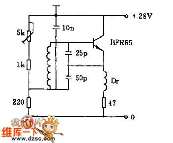
WIDEBAND_NOISE_GENERATOR
Published:2009/6/26 2:14:00 Author:May
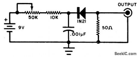
This circuit will produce wideband rf noise. It uses a reverse-biased diode and has a low-impedance output. Can be used to align receivers for optimum performance. (View)
View full Circuit Diagram | Comments | Reading(3470)
NOISE_GENERATOR
Published:2009/6/26 2:13:00 Author:May
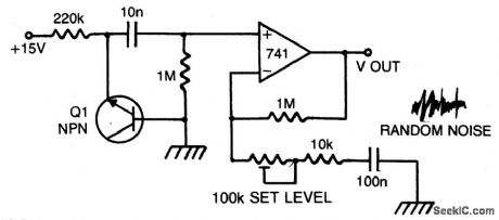
The zener breakdown of a transistor junction is used as a noise generator. The breakdown mechanism is random and this voltage has a high source impedance. By using the op amp as a high input impedance, high ac gain amplifier, a low impedance, large signal noise source is obtained. The 100K potentiometer is used to set the noise level by varying the gain from 40 to 20 dB. (View)
View full Circuit Diagram | Comments | Reading(0)
PINK_NOISE_GENERATOR
Published:2009/6/26 2:12:00 Author:May
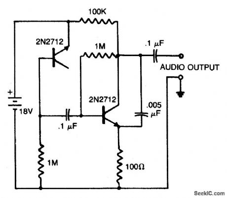
A reverse-biased pn junction of a 2N2712 transistor is used as a noise generator. The second 2N2712 is an audio amplifier. The 0.005 μF capacitor across the amplifier output remove s some high-frequency components to simulate pink noise more closely. The audio output may be connected to high-impedance earphones or to a driver amplifier for speaker listening. (View)
View full Circuit Diagram | Comments | Reading(0)
AUDIO_NOISE_GENERATOR
Published:2009/6/26 2:10:00 Author:May

This simple circuit generates both white and pin noise. Transistor Q1 is used as a zener diode. The normal base-emitter junction is reverse-biased and goes into zener breakdown at about 7 to 8 volts. The zener noise current from Q1 floirs into the base of Q2 such that an output of about 150 millivolts of white noise is available. To convert the white noise to pink, a filter is required which provides a 3 dB cut per octave as the frequency increases.Since such a filter attenuates the noise considerably an amplifier is used to restore the output level. Transistor Q3 is this amplifier and the pink noise filter is connected as a feedback network. between collector and base in order to obtain the required characteristic by controlling the gain-yersus-fre quency of the transistor. The output of transistor Q3 is thus the pink noise required and is fed to the relevant output socket. (View)
View full Circuit Diagram | Comments | Reading(3019)
NOISE_GENERATOR
Published:2009/6/24 5:12:00 Author:May
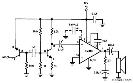
This noise generator uses a Zener diode. The transistors are part of the LM389. (View)
View full Circuit Diagram | Comments | Reading(0)
NOISE_GENERATOR
Published:2009/6/24 2:04:00 Author:May

This circuit generates noise pulses that are suitable for test purposes, etc. A zener diode is used as a noise source. IC1 is a relaxation oscillator. P1 determines noise bandwidth, and P2 and P3 the noise amplification. Current consumption is 10 mA @ 12 Vdc. (View)
View full Circuit Diagram | Comments | Reading(4)
Piezoelectric high level automatic control and alarming circuit
Published:2011/6/30 10:51:00 Author:John | Keyword: automatic control
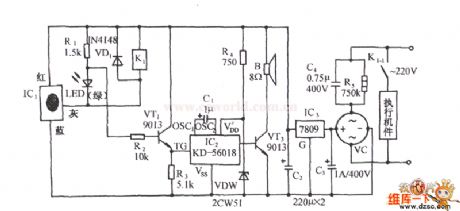
The shown circuit consists of the piezoelectric material level sensor, relay control mechanical circuit, analog voice circuit and AC buck rectifier circuit. When the material level rises to the high material level, the circuit can be issued for a given analog sound and also cut off the power supply of the feeding equipment. Then the feeding process stops in order to ensure safe operation. IC1 is a piezoelectric material level sensing circuit, which consists of self-excited oscillator, rectifier circuit, voltage comparator circuit and output stage of the open circuit.
(View)
View full Circuit Diagram | Comments | Reading(902)
Multi-functional sound generator composed of NE555、CC4051
Published:2011/4/18 20:13:00 Author:Ecco | Keyword: Multi-functional sound generator
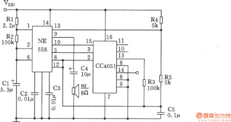
This circuit is mainly used for regular alarm and audio generator in electronic toys. The circuit is characterized by a large range of supply voltage changing adaptation, it can work under 4 ~ 18V. Tone and tempo do not change by the altering of supply voltage, it can be used to indicate various states.
(View)
View full Circuit Diagram | Comments | Reading(1743)
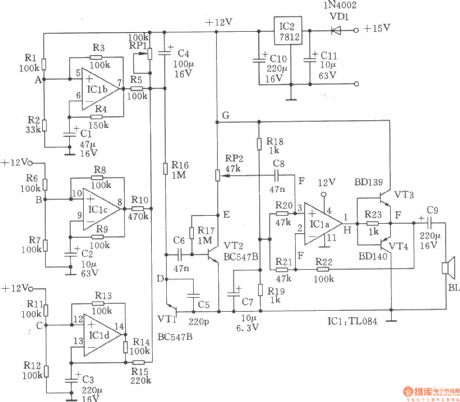
Homemade gunfire analog generator
Published:2011/4/14 2:45:00 Author:Ecco | Keyword: Homemade gunfire , analog generator
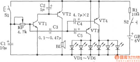
Two transistors form a complementary audio oscillator which could be used as gunfire analog sound generator, and the sounds are realistic, rich in reverberation. The circuit is as shown. Selection of components: transistor VTl, VT2: 9014, β = 85 ~ 115, VT3, VT4: 9015, β = 65 ~ 85. Sl: AN4, S2: KN3. LED VDl ~ VD6: BT201, can also choose other models, the best selection is the LED in low power, high luminous efficiency. Battery GB: 4F22DC6V stacked batteries. Speaker BL: 8Ω, 0.25W.
(View)
View full Circuit Diagram | Comments | Reading(1537)
Rain generator composed of NE555
Published:2011/4/14 2:45:00 Author:Ecco | Keyword: Rain generator
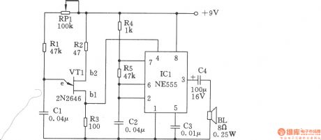
This circuit is very simple, it's composed of regular component, which includes two oscillators, one is a frequency oscillator of single-junction transistors VTl (2N2646) variable, VTl can oscillate without resonant coils, the circuit is shown in the chart.
(View)
View full Circuit Diagram | Comments | Reading(2205)
Simple seashore generator
Published:2011/4/14 2:46:00 Author:Ecco | Keyword: Simple, seashore generator
View full Circuit Diagram | Comments | Reading(984)
Noise generator with various sounds composed of HT2880
Published:2011/4/12 0:52:00 Author:Ecco | Keyword: Noise generator , various sounds
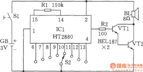
This circuit can produce eight kinds of sounds, that are two kinds of guns' sounds, two bomb sounds, dual-tone melody, the game sound, animal sounds and the sound of rifles. The eight sounds can be played by rotary switch S2 and button switch. HT2880 is a CMOS LSI's ROM chip. In the circuit, the transistors VT1 and VT2 connects as Darlington tubes, they are used as forecast the output signal of pins. (View)
View full Circuit Diagram | Comments | Reading(2184)
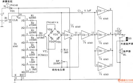
Noise generator composed of CH4040
Published:2011/4/12 0:38:00 Author:Ecco | Keyword: Noise generator
View full Circuit Diagram | Comments | Reading(923)
Circuit Categories
power supply circuit
Amplifier Circuit
Basic Circuit
LED and Light Circuit
Sensor Circuit
Signal Processing
Electrical Equipment Circuit
Control Circuit
Remote Control Circuit
A/D-D/A Converter Circuit
Audio Circuit
Measuring and Test Circuit
Communication Circuit
Computer-Related Circuit
555 Circuit
Automotive Circuit
Repairing Circuit