
Oscillator Circuit
Index 21
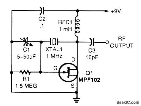
PIERCE_ORYSTAL_OSCILLATOR
Published:2009/7/12 23:17:00 Author:May
View full Circuit Diagram | Comments | Reading(1056)
CMOS_CRYSTAL_OSCILLATOR
Published:2009/7/12 23:16:00 Author:May
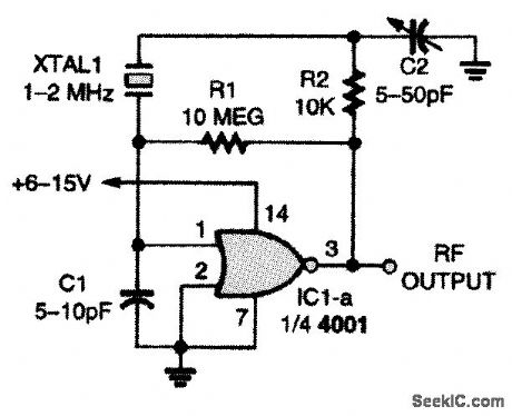
This single CMOS two-input NOR-gate crystal oscillator circuit has one major limitation: It lacks high-frequency performance. Otherwise, it is a solid performer. (View)
View full Circuit Diagram | Comments | Reading(0)
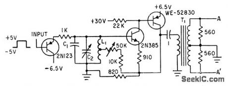
VERSATILE_WIDEBAND_ORYSTAL_OSCILLATOR
Published:2009/7/12 23:15:00 Author:May
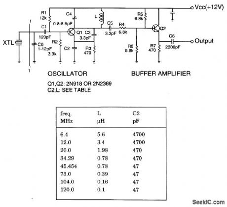
The crystal oscillator operates from 6 to 120 MHz by changing only C2 and L. The table lists component vaues for crystal oscillator at different frequencies. (View)
View full Circuit Diagram | Comments | Reading(1041)
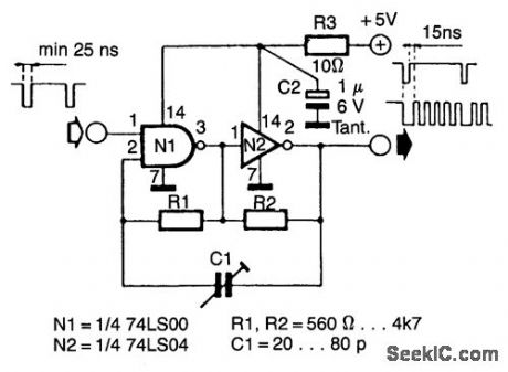
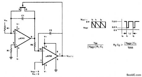
FAST_LOW_DUTY_CYCLE_PULSE_OSCILLATOR
Published:2009/7/16 22:05:00 Author:Jessie
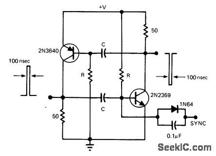
This simple and symmetrical free-running generator has a 50-Ω output impedance, a pulse width of 100 ns and complementary outputs that swing essentially from ground to the power-supply voltage. Moreover, it functions with a power supply range from < 1 to > 15 V and maintains a low voltage and temperature drift while consuming little power.
For oscillation to occur, each transistor must have a gain greater than unity. This restricts the value of R to a range of 1 kΩ to 1 MΩ, because the gain will be less than unity when the transistor is saturated or when beta is low as a result of small collector currents. The two RC timing networks do not have to match because the RC with the longest time constant will determine the frequency of oscillation. (View)
View full Circuit Diagram | Comments | Reading(948)
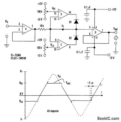
STABLE_START_STOP_OSCILLATOR
Published:2009/7/16 22:03:00 Author:Jessie
Oscillators that generate a predetermined number of pulses are often required in applications such as video work. This oscillator starts 13 ms after the control signal goes high and stops immediately when the input signal goes low. (View)
View full Circuit Diagram | Comments | Reading(957)
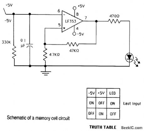
SCHMIDT_TRIGGER_MEMORY_CELL_CIRCUIT
Published:2009/7/16 21:55:00 Author:Jessie
View full Circuit Diagram | Comments | Reading(969)
SHOCK_EXCITED_COSINE_WAVE_OSCILLATOR
Published:2009/7/16 21:53:00 Author:Jessie
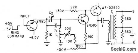
Single 34.1-mlcrosec ring command turns on five identical harmonic generators for alphanumeric character generator.-K. E. Perry and E. J. Aho,Radar-Computer Display Traces Alphanumeric Characters, Electronics, 34:26, p 75-79. (View)
View full Circuit Diagram | Comments | Reading(729)
SHOCK_EXCITED_SINE_WAVE_OSCILLATOR
Published:2009/7/16 21:51:00 Author:Jessie
Rectangular pulse turns on five identical harmonic generators for alphanumeric character generator.-K. E. Perry and E. J. Aho, Radar-Computer Display Traces Alphanumeric Charactors, Electronics, 34;26, p 75-19. (View)
View full Circuit Diagram | Comments | Reading(775)
PHOTOVOLTAIC_ISOLATOR_CIRCUIT
Published:2009/7/16 22:59:00 Author:Jessie
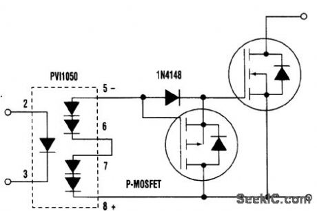
The advantage of the programmable junction transistor (PUT) over a P-MOSFET used as a gate pull-down is that the PUT will pull the gate well below the MOSFET threshold voltage much faster at lower cost. The PUT can discharge a gate capacitance of 5 nF at 12V in 100 ns. (View)
View full Circuit Diagram | Comments | Reading(1251)
CODE_PRACTICE_OSCILLATOR
Published:2009/7/12 20:49:00 Author:May
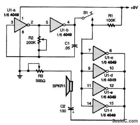
This versatile code-practice oscillator has a variable frequency and volume control. The unit is especially suitable for use by small groups that are interested in learning and practicing code. A single 4049 CMOS hex inverting buffer is the heart of the oscillator, with inverters U1-a and U1-b making up the variable audio-oscillator circuit. The oscillator's output is coupled to the speaker-driver circuit through the CW (Morse code) key S1. The audio frequency of the oscillator (hence, its tone) is varied by the potentiometer. R3 is used to vary the speaker's volume. (View)
View full Circuit Diagram | Comments | Reading(0)
RAMP_GENERATOR_DRIVES_TRlGGER
Published:2009/7/19 21:39:00 Author:Jessie
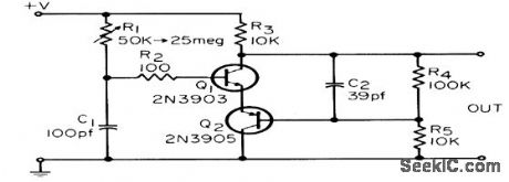
Circuit is relaxation oscillator providing short, fast pulses for triggering mvbr. Upper operating frequency is about 1 Mc for values shown. Efficiency is high yet total component cost is under $2.-C. F. Andren, High Efficiency Relaxation Oscillator, EEE, 14:4, p 43. (View)
View full Circuit Diagram | Comments | Reading(949)
TOUCH_OPERATED_CODE_PRACTICE_OSCILLATOR
Published:2009/7/12 20:43:00 Author:May
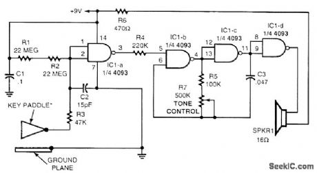
A touch-operated CPO is shown in the figure. The gates of IC1-a are biased high through the two 22-MΩ resistors (R1 and R2), keeping its output low. Gates IC1-b and IC1-c are connected in an audio oscillator circuit that can operate only when pin 5 of IC1-b is high. The last gate of the 4093, IC1-d, adds isolation to the oscillator's circuit and drives the speaker (SPKR1). Touching the key paddle and ground plane lowers IC1-a's input gate voltage to near zero, allowing the output at pin 3 to go high. The tone generator then turns on and sends out an audio note. The touch key paddle and ground plane can be made from a circuit board or any other conductible material. Note that the ground plane should lie flat for a hand rest and the key paddle should be positioned for ease of touch. (View)
View full Circuit Diagram | Comments | Reading(998)
PLL_CODE_PRACTICE_OSCILLATOR
Published:2009/7/12 20:41:00 Author:May

This CPO usesa 567 phase-locked loop, IC1, as the variable tone generator. The oscillator's frequency is set by R6, and the frequency range can be changed by selecting a different-value capacitor for C5. To lower the oscillator's frequency range, make the value of C5 larger, and to increase the frequency range, reduce C5. A general-purpose 2N3906 PNP transistor, Q1, supplies power to the 567 through pin 4 each time that the CW key is closed. Meanwhile, Q2, a general-purpose 2N3904 NPN transistor, buffers the oscillator's output and drives the speaker. Potentiometer R7 sets the output volume. (View)
View full Circuit Diagram | Comments | Reading(1179)
MORSE_CODE_OSCILLATOR
Published:2009/7/12 20:38:00 Author:May
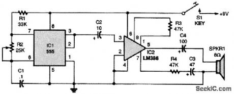
The circuit is built around a 555 oscillator (IC1) and an LM386 audio amplifier (IC2). The 555 circuit is an astable oscillator, with the chip output retriggering the circuit. When the key (S1) is pressed, it activates the circuit. The 555 oscillates at a frequency determined by R1, R2, and C1. Potentiometer R2 is used to adjust the tone frequency of the oscillator. Some of the output current of IC1 is coupled to IC2 via a 10-°F capacitor, C2, so that it will be sufficient to drive a loudspeaker. Because the circuit has no gain control, the volume depends on the size and wattage of the speaker. (View)
View full Circuit Diagram | Comments | Reading(2497)
PRACTICE_OSCILLATOR
Published:2009/7/11 5:04:00 Author:May

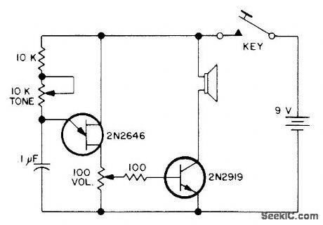
Simple design provides for adjustment of both volume and tone.-Circuits, 73 Magazine, July 1974, p 81. (View)
View full Circuit Diagram | Comments | Reading(942)
STABILIZED_LOW_FREQUENCY_OSCILLATOR
Published:2009/7/11 4:36:00 Author:May
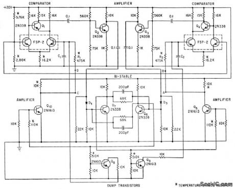
Transistors Q1 and Q4 compare charging voltages of mvbr timing capacitors C1 and C2 to fixed reference voltage.When a capacitor voltage is greater than reference.its comparator switches its bistablw mvbr to opposite state,so capacitor is discharged by dump transistor.Arrangement makes output frequency essentially independent of temperqture from-25℃ to+75℃.for frequency range of 0.01 to 100,000 cps,-J.D.Long.Novel Differential Amplifier Stabilizes Multivibrator,Electronics,35:24,p53-54 (View)
View full Circuit Diagram | Comments | Reading(870)
VCO
Published:2009/7/11 4:31:00 Author:May

Q1. an FET. is used as a variable resistance to control frequency of oscillator. (View)
View full Circuit Diagram | Comments | Reading(0)
VARACTORLESS_VCO
Published:2009/7/11 4:28:00 Author:May
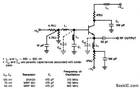
The varactorless VCO utilizes a modifted Clapp-oscillator conftguration, together with some data on the type of transistor, circuit values, and operating frequencies. (View)
View full Circuit Diagram | Comments | Reading(965)
WIDE_RANGE_VCO
Published:2009/7/11 4:24:00 Author:May
This circuit covers 0 to 1.4 kHz.C1 can be changed to cover other ranges,as desired. (View)
View full Circuit Diagram | Comments | Reading(1213)
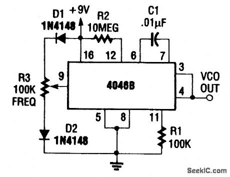
BIPHASE_WIDE-RANGE_VCO
Published:2009/7/11 4:21:00 Author:May
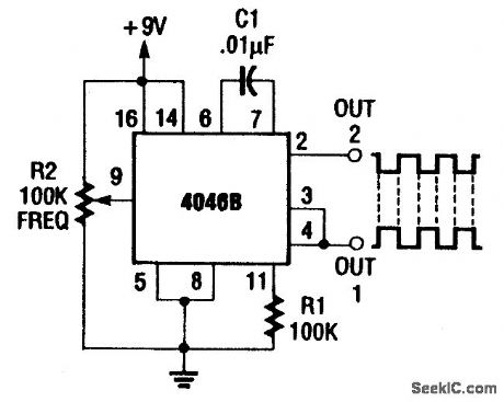
Using a CD4046B, this circuit generates abiphase signal.The frequency range is below 100Hz to about 1.5 kHz. (View)
View full Circuit Diagram | Comments | Reading(2049)
| Pages:21/54 At 202122232425262728293031323334353637383940Under 20 |
Circuit Categories
power supply circuit
Amplifier Circuit
Basic Circuit
LED and Light Circuit
Sensor Circuit
Signal Processing
Electrical Equipment Circuit
Control Circuit
Remote Control Circuit
A/D-D/A Converter Circuit
Audio Circuit
Measuring and Test Circuit
Communication Circuit
Computer-Related Circuit
555 Circuit
Automotive Circuit
Repairing Circuit