
Oscillator Circuit
Index 20
TRANSFLUXOR_OSCILLATOR
Published:2009/7/16 3:15:00 Author:Jessie
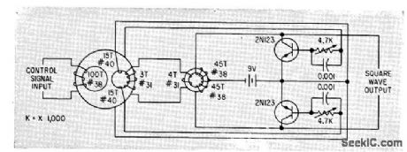
Holds frequency setting for many hours after removal of control signal. Operates between 100 kc and 1 Mc. Gives square-wave output.-R. J. Sheirn, Transfluxor Oscillator Gives Drift-Free Output, Electronics, 33:10, p 48-49. (View)
View full Circuit Diagram | Comments | Reading(1511)
2_23_MHz_UNTUNED_OSCILLATOR
Published:2009/7/13 21:37:00 Author:May
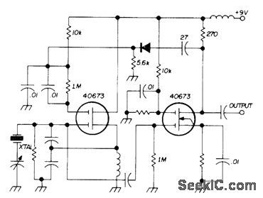
Two dualgate MOSFETs operate in untuned Colpitts crystal oscillator Used in SSB transceiver made by Sideband Associates for radiomarine communication in 2-23 MHz range Oscillator feeds isolating amplifier,Small capacitor can be used for netting individual crystal to precise assigned frequency.-E Noll, MOSFET Circuits, Ham Radio Feb 1975,p50-57. (View)
View full Circuit Diagram | Comments | Reading(1507)
9_MHz_CRYSTAL
Published:2009/7/13 21:27:00 Author:May
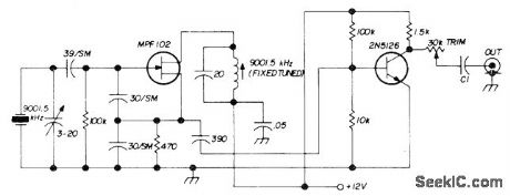
Used in transmitter section of 80-meter 10-W SSB transceiver. Value of C1 is 50-330 pF, chosen for desired output range. Carrier level can be adjusted with slug-tuned coil or with 30K trimpot.-D. Hembling, Solid State 80-Meter SSB Transceiver, Ham Radio, March 1973, p 6-17. (View)
View full Circuit Diagram | Comments | Reading(1627)
VOLTAGE_CONTROLLED_OSCILLATOR
Published:2009/7/13 5:15:00 Author:May
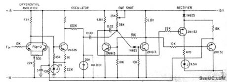
Simple circuit,using feedback to maintain accuracy,converts 0 to 3V d-c linearly to 0 to 400 cps.Uses differential amplifier that amplifies difference between input and feedback signals and feeds frequency-determining output to Shockley four-layer diode oscillator-J. D.Long, Feedback linearizes Voltage-To-Frequency Converter, Electronics, 34:35, p48. (View)
View full Circuit Diagram | Comments | Reading(0)
TRANSDUCER_DRIVEN_CRYSTAL_OSCILLATOR
Published:2009/7/13 5:07:00 Author:May
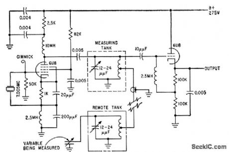
Sensitive 70-Mc one-tube oscillator feeds local and remote tank circuits to which capacitive or inductive transducers may be connetted, for conversion of displacement, temperature, pressure, and other variables to corresponding changes in d-c output voltage.Will give up to 250V change per micromicro-farad of transducer capacitance change.-L. J.Rogers, Sensitive Transducers Use One-Tube Crystal Oscillator, Electronics, 32:40, p48-49. (View)
View full Circuit Diagram | Comments | Reading(1414)
SWEPT_OSCILLATOR_FOR_HAM_BAND_ANTENNA_TUNING
Published:2009/7/13 3:39:00 Author:May
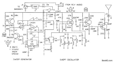
Transistor Q1 acts as a constant-current generator, charging capacitor C1 at a rate determined by the value of R1. The high input impedance of U1b ensures that the constant-current generator is not excessively loaded and forwards the voltage level of C1 to U1c. U1c is configured as a comparator, and output pin 8 goes low when pin 9 rises above 9 V. This switching action applies a trigger pulse via capacitor C2 to activate the monostable multivibrator, U2. The resulting high pulse from pin 3 of U2 provides a discharge path for capacitor C1 through turned-on transistor Q2. A continuous sweep ramp with reset is produced at pin 7 of Ulb at a rate determined by RIC1 (approximately 75 Hz). The swept oscillator section consistsof a dual-gate MOSFET transistor in a Colpitts configuration, followed by a buffer amplifier that provides the RF from the selected frequency range to an output amplifier and short antenna. As the output sawtooth waveform from U2, pin 7, is applied to the varactor, the capacitance of the tank circuit decreases from approximately 62 pF at the low end of the ramp to a very low value at the maximum sweep level of about 9.2 V. The on-off switching action of the sweep waveform modulates the generated RF to produce an obnoxious buzz, which is easy to differentiate from other low-level signals at the selected receiver frequency when adjusting the tuner or antenna.
(View)
View full Circuit Diagram | Comments | Reading(1188)
PULSED_OSCILLATOR
Published:2009/7/16 5:35:00 Author:Jessie
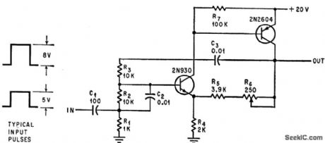
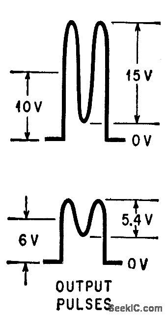
Circuit is pulsed on only when required ,as in tone generators where output is needed only occasionally and power must be conserved. Uses Wien-bridge oscillator have rang of 100 cps to 100 kc, which operates only when gating pulse is applied to input. Amplitude of output oscillations varies with amplitude of gating pulsed.-R.C. Lavigne and L. L. Kleinberg, Pulsed Oscillator Conserves Power, Electronics, 39:17, p 98-99. (View)
View full Circuit Diagram | Comments | Reading(1260)
MULTI_WAVEFORM_OSCILLATOR
Published:2009/7/16 5:31:00 Author:Jessie
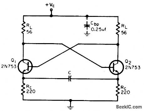
By varying collector load, emitter resistors, and C, oscillator can produce triangular wave, square wave up to 30 Mc, microwattt audio signal, or serve as voltage-controlled oscillator. Values shown, with 6.v supply and 0.01 mfd mined for C, give 0.8 V peak-to-peak square wave at about 1 Mc. –P. Lefferts, Multi-Oscillator Gives Simple Waveforms, 30-Mc Output, EEE, 12:10, P 60. (View)
View full Circuit Diagram | Comments | Reading(1194)
3_kV_FOR_CRO
Published:2009/7/13 2:38:00 Author:May
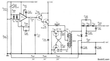
Circuit also provides 1-kV negative supply at 2 mA, as required for cathoderay tube of oscilloscope. Positive supply furnishes 50 μA at 3 kV. Design uses transistor inverter operating at about 20 kHz to simplify filtering. Tr82 and Tr83 form current-switched class D oscillator producing sine waves at high efficiency. Current multiplication is provided by Tr80 and Tr81 for 709 IC opamp.-C.M. Little,A 50 MHz Oscilloscope, Wireless World, July 1975,p 319-322. (View)
View full Circuit Diagram | Comments | Reading(2356)
MACHINE_GUN_CONTROL_OSCILLATOR
Published:2009/7/13 2:22:00 Author:May
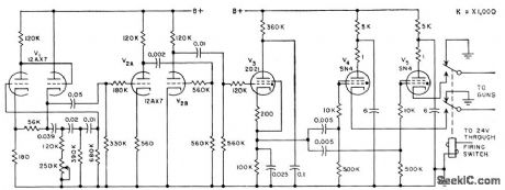
Phase-shift oscillator firing circuit for airborne 20-mm guns permits operation anywhere in range of 600 to 900 rounds per minute,Accuracy is improved by adjusting firing rate away from natural gun-mount vibration frequency.-M. Halio, Firing Circuits Trigger Airborne Machine Guns, Electronics, 31:31, p 86-89. (View)
View full Circuit Diagram | Comments | Reading(1036)
State variable oscillation circuit diagram
Published:2011/8/4 1:53:00 Author:Ecco | Keyword: State variable oscillation
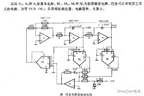
Op amps A1, A2 and A3 are the basic circuits, and M1. , M2, M3 and M4 use the shock stabilizing circuit, but can also use other forms of circuits. The VCA uses the analog multiplier, which is simple with low distortion.
(View)
View full Circuit Diagram | Comments | Reading(1077)
QUARTZ_CRYSTAL_SPECIFICATIONS
Published:2009/7/12 23:49:00 Author:May
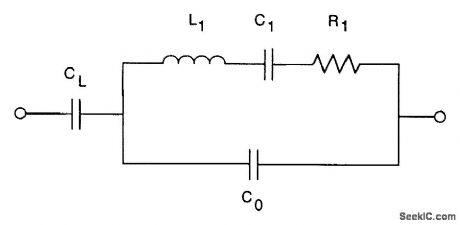


Five main parameters control the characteristics of a crystal, as noted in the equivalent circuit for the figure. These parameters are:
● C1, the motional capacitance● L1, the motional inductance● R1, the equivalent series resistance (ESR)● C0, the parallel capacitance resulting from the electrodes and crystal packaging● CL, external load capacitanbe of the circuit
C1 and L1 are interdependent because they determine the resonant frequency of the crystal. If we know one of the parameters, we can readily compute the other if we know the series resonant frequency. R1 is the resistance determined by the motional (piezoelectric) behavior of the crystal. If it is too high, the crystal might not start oscillation. C0 is a physical capacitor, created by the electrodes plated onto the crystal surface, along with some additional capacitance from the package. Generally, larger C0 contributes to better pullability. CL is the load capacitance of the user's circuit. The crystal must operate at the right frequency in the intended circuit, so this value needs to be included in the crystal purchase specification. (View)
View full Circuit Diagram | Comments | Reading(1303)
SYNC_BLOCKING_OSCILLATOR
Published:2009/7/16 21:20:00 Author:Jessie
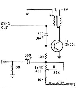
Free-running period of grounded-emitter stage is made to lock in with frequency of pulse generator, to provide synchronizing signal for conventional oscilloscope during tests of high-speed computer circuits.-L. Neumann, Transistorized Generator for Pulse Circuit Design, Electronics, 32:14, p 47-49. (View)
View full Circuit Diagram | Comments | Reading(987)
COLPITTS_ORYSTAL_OSCILLATOR
Published:2009/7/12 23:29:00 Author:May
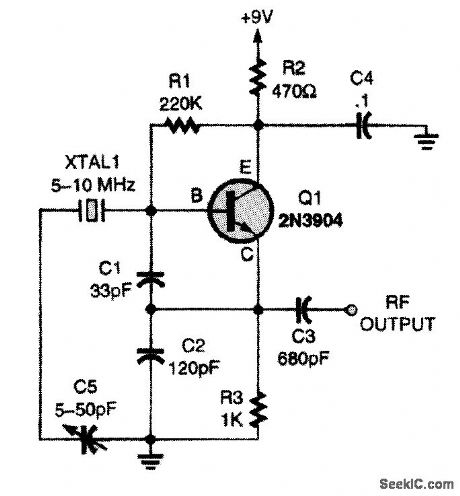
This circuit is commonly called a Colpitts oscilLcttor. C1 and C2 determine the feedback ratio that maintains oscillation. To obtain maximum frequency stability and output level, C1 and C2 should be selected for a given frequency. (View)
View full Circuit Diagram | Comments | Reading(1066)
TTL_ORYSTAL_OSCILLATOR
Published:2009/7/12 23:28:00 Author:May
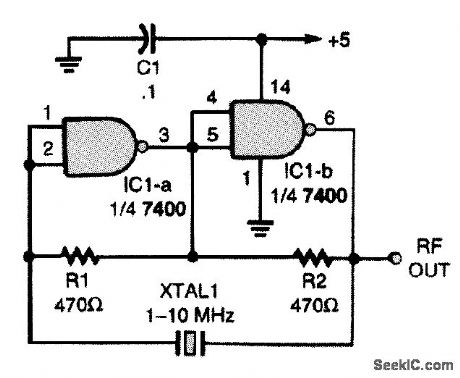
Here is an oscillator circuit that uses no L/C components. It uses two sections of a 7400 TTL IC, two resistors, and a crystal to make up a simple and stable oscillator circuit. (View)
View full Circuit Diagram | Comments | Reading(3036)
32768_kHz_MICROPOWER_OSCILLATOR
Published:2009/7/12 23:27:00 Author:May
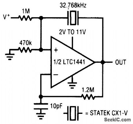
Using an LTC1441, this oscillator pulls 9 μA at a supply voltage of 2 V. The circuit has no spurious modes. (View)
View full Circuit Diagram | Comments | Reading(1484)
BASIC_NE602_COLPITTS_CRYSTAL_OSCILLATOR
Published:2009/7/12 23:26:00 Author:May
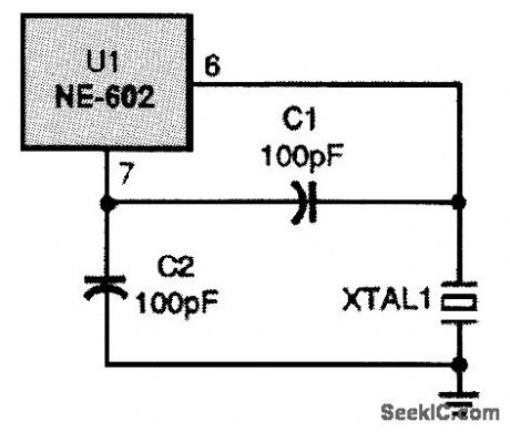
This basic Colpitts crystal oscillator will work with fundamental-mode crystals up to 20 MHz. (View)
View full Circuit Diagram | Comments | Reading(1450)
NE602_ADJUSTABLE_ORYSTAL_OSCILLATOR
Published:2009/7/12 23:25:00 Author:May
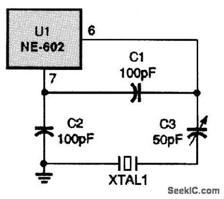
Here, a variable capacitor is added to the circuit to make it easier to obtain the desired frequency. (View)
View full Circuit Diagram | Comments | Reading(921)
NE602_THIRD_OVERTONE_CRYSTAL_OSCILLATOR
Published:2009/7/12 23:20:00 Author:May
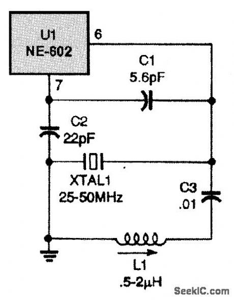
This overtone crystal oscillator uses thirdovertone crystals and will work from 25 to 50 MHz. (View)
View full Circuit Diagram | Comments | Reading(1218)
NE602_OVERTONE_ORYSTAL_OSCILLATOR
Published:2009/7/12 23:18:00 Author:May
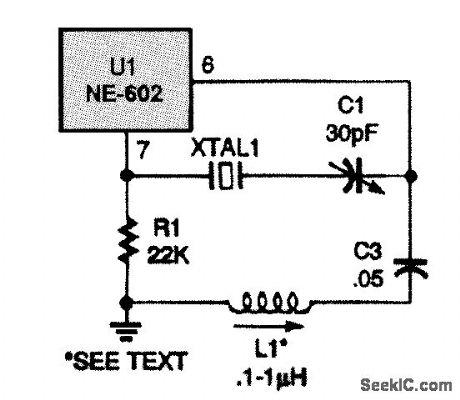
For higher frequencies, use an overtone crystal oscillator like the one shown here. The circuit is a Butler oscillator. The overtone crystal is connected between the oscillator emitter of the NE602 (pin 7) and a capacitive voltage divider that is connected between the oscillator base (pin 6) and ground. An inductor is also in the circuit (L1),and it must resonate with C1 to the overtone frequency of crystal XTAL1. The circuit can use either third- or fifth-overtone crystals up to about 80 Fig. 24-4 MHz. (View)
View full Circuit Diagram | Comments | Reading(2624)
| Pages:20/54 1234567891011121314151617181920Under 20 |
Circuit Categories
power supply circuit
Amplifier Circuit
Basic Circuit
LED and Light Circuit
Sensor Circuit
Signal Processing
Electrical Equipment Circuit
Control Circuit
Remote Control Circuit
A/D-D/A Converter Circuit
Audio Circuit
Measuring and Test Circuit
Communication Circuit
Computer-Related Circuit
555 Circuit
Automotive Circuit
Repairing Circuit