
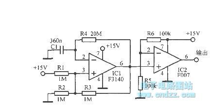
Oscillator Circuit
Index 7
Oscillator circuit diagram with triangle-wave/square wave output
Published:2012/8/30 1:29:00 Author:Ecco | Keyword: Oscillator, triangle wave, square wave
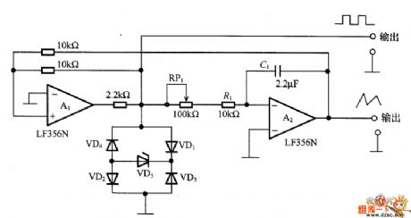
The circuit is composed of lag comparator with A1 and inverting integrator A2, and the charging and discharging time constant is decided by integral resistors (R1+RP1) and the capacitor C1. VD1~VD5 form the limiter circuit. The maximum oscillation frequency is related to swicthing rate of amplifier, when swicthing rate is 10V/μ s, in order to get the 20V (peak-peak) triangle wave, it must have at least 2 μ s lag, even up to 20 μ s, therefore, in order to increase the frequency of oscillation, A1 and A2 should select high speed operational amplifier.
(View)
View full Circuit Diagram | Comments | Reading(3140)
1000 m single-tube oscillation (C8050) FM transmitter circuit
Published:2012/8/27 22:27:00 Author:Ecco | Keyword: 1000 m , single-tube oscillation , FM transmitter
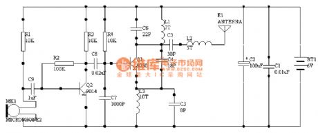
The circuit is very simple without debugging, you just need to make sure components are well connected without rosin joint and short circuit, it can work properly. Its power is about 60mw, so it is generally recommended to use rechargeable batteries which not only can provide large current, and be economy, and it is the ideal choice. But I do not advocate the transformer power supply, because it needs high filter circuit.
(View)
View full Circuit Diagram | Comments | Reading(2819)
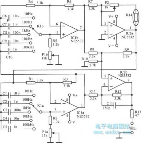
High-performance audio oscillator
Published:2012/8/27 1:02:00 Author:Ecco | Keyword: High-performance audio oscillator
View full Circuit Diagram | Comments | Reading(1244)
Low frequency oscillator circuit with TcA580
Published:2012/8/22 20:18:00 Author:Ecco | Keyword: Low frequency , oscillator
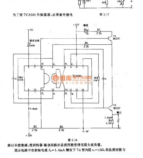

In order to use TCA580 as oscillator, the circuit must connect an external circuit for attenuation, then the loop - oscillation loop's quality factor becomes infinite or negative. In the circuit shown as the figure, when emitter current IE =1.6mA, internal resistance of T4 tube re= 16Ω.
(View)
View full Circuit Diagram | Comments | Reading(1472)
Ultra-low frequency multivibrator
Published:2012/8/21 22:46:00 Author:Ecco | Keyword: Ultra-low frequency , multivibrator
View full Circuit Diagram | Comments | Reading(769)
Pulse keying ring oscillator
Published:2012/8/21 22:08:00 Author:Ecco | Keyword: Pulse, keying, ring , oscillator
View full Circuit Diagram | Comments | Reading(1451)
The circuit of 100kHz oscillator
Published:2012/8/21 3:40:00 Author:Ecco | Keyword: 100kHz oscillator

The circuit uses a standard quartz crystal oscillator SQ4804A, and the bias between output frequency and standard frequency does not exceed 100 × 10-6. The oscillator control the following amplifier (BC108) to output square wave, and it uses the integral circuit to obtain up to 8 branches of output, then to control the eight gates.
(View)
View full Circuit Diagram | Comments | Reading(2587)
1kHz to 1MHz sine oscillator circuit
Published:2012/8/21 21:03:00 Author:Ecco | Keyword: 1kHz to 1MHz , sine oscillator
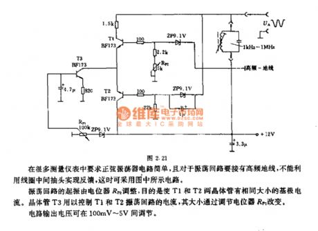
Sinusoidal oscillator circuit issimple in many measuring instrument, and oscillation loop should be connected to a high-frequency ground, and it can not use the coil center tap to achieve the feedback, in this case it can use the circuit shown as figure. The oscillation starting of shock drop is adjusted by potentiometer RP2, the purpose is to make T1 and T2 transistors have the same base current. Transistor T3 is used for controlling the current of T1 , T2 oscillation loop, and its size is changed by adjusting potentiometer RP1. Circuit output voltage can be adjusted between 100mV ~ 5V.
(View)
View full Circuit Diagram | Comments | Reading(1534)
Astable flip-flop ( multivibrator ) circuit
Published:2012/8/21 20:25:00 Author:Ecco | Keyword: Astable flip-flop , multivibrator
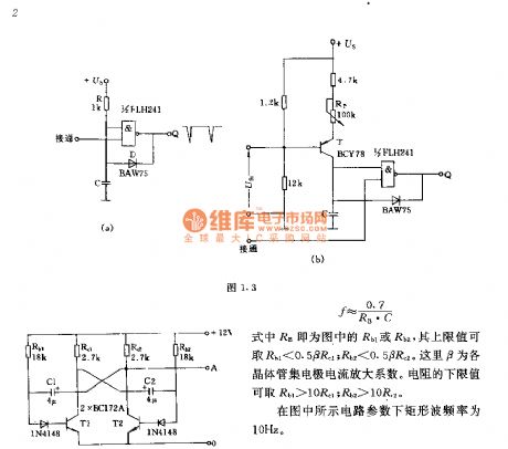
The two parts' component parameters and models of the circuit are corresponding to simultaneously obtain a rectangular wave with duty ratio of 1:1, its frequency f = 0.7/RB • C. RB is Rb1 or Rb2 in the figure, and its upper limit value Rb1 < 0.5βRC1 ; Rb2 < 0.5βRC2, here β is the transistor collector current amplification factor. The lower limit value of the resistor is Rb1 > 10βRC1 ; Rb2 > 10βRC2, the of rectangular wave frequency under circuit parameters shown in figure is 10Hz.
(View)
View full Circuit Diagram | Comments | Reading(1928)
Oscillator for electronic musical instruments
Published:2012/8/21 3:48:00 Author:Ecco | Keyword: Oscillator , electronic musical instruments
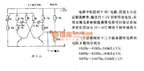
The circuit comprises two RC circuits, the value can determine the oscillation frequency. The output rectangular wave voltage is approximately 7.5V. It uses metallized polycarbonate film capacitor to guarantee that the frequency deviation is less than 0.5% in the temperature range of 10 ~ 40 ℃. The R values of 12 oscillators in an octave process are selecting as below.
(View)
View full Circuit Diagram | Comments | Reading(1009)
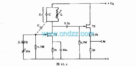
Common-base quartz controlled frequency capacitance feedback oscillator
Published:2012/8/21 20:02:00 Author:Ecco | Keyword: Common-base , quartz , controlled frequency , capacitance feedback , oscillator
View full Circuit Diagram | Comments | Reading(1019)
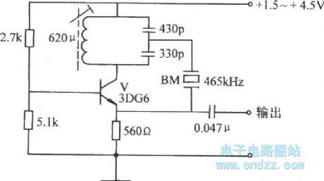
The LC oscillator circuit for electronic cello
Published:2012/8/21 20:00:00 Author:Ecco | Keyword: LC oscillator , electronic cello
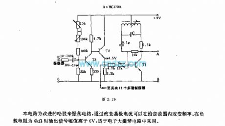
This circuit is the improved hartley oscillator circuit, changing the base current can adjust the frequency in a given range. The output signal amplitude is higher than 6V in 6kΩ load resistance,and it is suitable for electronic cello circuits.
(View)
View full Circuit Diagram | Comments | Reading(1929)
Simple sinusoidal oscillator
Published:2012/8/13 20:56:00 Author:Ecco | Keyword: sinusoidal oscillator
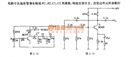
The oscillation signal is adjusted by the potentiometer Rp1. The output resistor is low ( 1kΩ ), so it is applied to a variety of control circuits for the signal source. In the circuit, the transistor collector through R1 , R2, , C1, , C2 to the base and constitutes the feedback branch. Changing the parameters of these components can change the frequency range.
(View)
View full Circuit Diagram | Comments | Reading(1114)
Simple single field-effect transistor oscillator circuit
Published:2012/8/12 22:19:00 Author:Ecco | Keyword: Simple , single , field-effect transistor , oscillator
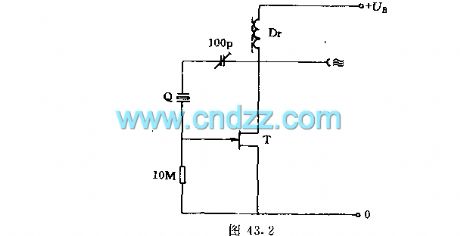
This circuit uses a field-effect transistor to constitute a quartz crystal oscillator circuit with excellent performance, the tuning capacitor is used to adjust the scope, and choke can be selected according to the frequency range to make WL be greater than 20kΩ.
(View)
View full Circuit Diagram | Comments | Reading(1672)
100MHz power oscillator circuit using dual- gate FET
Published:2012/8/12 22:35:00 Author:Ecco | Keyword: 100MHz , power oscillator , dual- gate , FET
The oscillator uses tuning resonant circuit as the working resistor of the FET. Oscillating power signal is output by the fast switching transistors T1 and T2.
(View)
View full Circuit Diagram | Comments | Reading(2324)
Crystal quartz crystal oscillator circuit using FET
Published:2012/8/12 22:41:00 Author:Ecco | Keyword: Crystal , quartz , crystal , oscillator , FET
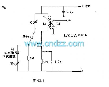
Crystal oscillator works as 51MHz crystal( the third harmonic of 17MHz) . According to the different structures, the drain - gate capacitance can be selected between 0.5 to 1.8 pF. L2's turns are about 20% of the L1. 470 Ω source resistor can change the oscillation characteristics.
(View)
View full Circuit Diagram | Comments | Reading(1930)
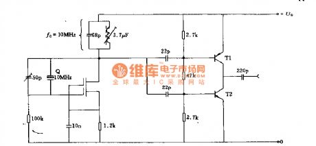
Fundamental Pierce oscillator circuit
Published:2012/8/12 22:29:00 Author:Ecco | Keyword: Fundamental Pierce , oscillator
The oscillator uses a fundamental quartz crystal, and the oscillation frequency can be up to 10MHz. Oscillator circuit is tuned to the resonant frequency. Capacitor C requires below 4.7pF, and it is connected to a follower to isolate the quartz crystal circuit.
(View)
View full Circuit Diagram | Comments | Reading(2366)
The quartz crystal oscillator circuit using NAND gate
Published:2012/8/12 22:31:00 Author:Ecco | Keyword: quartz crystal oscillator , NAND gate
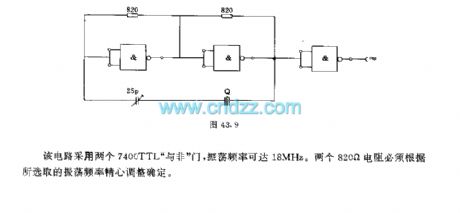
The circuit uses two 7400 TTL NAND gates, the oscillator frequency can reach 18MHz. Two 820 Ω resistors must be selected by oscillator frequency.
(View)
View full Circuit Diagram | Comments | Reading(2363)
555 dual astable multivibrator circuit diagram
Published:2012/7/23 3:10:00 Author:Ecco | Keyword: 555, dual astable multivibrator


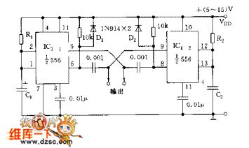
The circuit includes two synchronized multivibrators which are composed ofone pair of 555time base circuits. The circuit can output two synchronized pulse signals ,and the spacing and frequency can be changed by adjusting the time constant. The circuit is flexible and convenient.
When C1=C2=C, the oscillation frequency
The ducy cycle depends on the value of R1 and R2, and it can reach 5% ~ 95%.
(View)
View full Circuit Diagram | Comments | Reading(3558)
Bistable multivibrator circuit diagram
Published:2012/7/11 2:00:00 Author:Ecco | Keyword: Bistable multivibrator


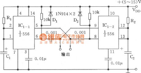
As shown in the figure, the circuitaretwo synchronized multivibrators composed of composed of two dualtime-base circuits 556, and itcan output two synchronous clock pulse signals, and the spacing and oscillation frequency can be changed by adjusting the time constant. It isflexibleand convenient. When you select C1 = C2 = C3 , the oscillation frequency is
.
The duty cycle D depends on R1 and R2, which can reach 5%~95%.
(View)
View full Circuit Diagram | Comments | Reading(1979)
| Pages:7/54 1234567891011121314151617181920Under 20 |
Circuit Categories
power supply circuit
Amplifier Circuit
Basic Circuit
LED and Light Circuit
Sensor Circuit
Signal Processing
Electrical Equipment Circuit
Control Circuit
Remote Control Circuit
A/D-D/A Converter Circuit
Audio Circuit
Measuring and Test Circuit
Communication Circuit
Computer-Related Circuit
555 Circuit
Automotive Circuit
Repairing Circuit