
Oscillator Circuit
Index 18
Digital lock 7
Published:2011/8/8 3:13:00 Author:Ecco | Keyword: Digital lock
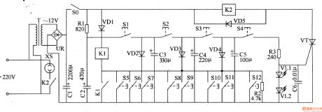
The digital lock circuit is composed of the password control circuit and sound and alarm circuir, and it is shown in Figure 3-104. Password control circuit consists of password buttons SO-S2, thyristors VTl-VT3, resistors Rl-R3, light-emitting diode VL and solenoid YA. Sound and alarm circuit consists of the error buttons S3-S9, thyristor VW, resistors R4-R8, voice integrated circuit ICl, audio power amplifier integrated circuit IC2, voltage regulator diode VS, capacitors Cl-C5 and the speaker BL. Rl-R4 and R6-R8 use the 1/4W carbon film resistors or metal film resistors; R5 select the 1/2W metal film resistor.
(View)
View full Circuit Diagram | Comments | Reading(817)
The multivibrator with variable duty cycle circuit diagram composed of Schmitt trigger
Published:2011/8/4 1:56:00 Author:Ecco | Keyword: multivibrator, variable duty cycle, Schmitt trigger
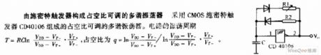
It is the multivibrator with variable duty cycle composed of Schmitt trigger CD40106.
(View)
View full Circuit Diagram | Comments | Reading(976)
TWO_PHASE_OSCILLATOR
Published:2009/7/14 22:11:00 Author:Jessie
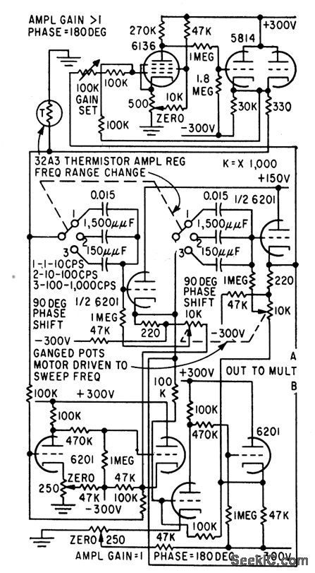
Unknown signal to be analyzed is multiplied independently by each of two output reference signals, A and B. Oscillator uses two 90° phase-shift networks and 180° of phase shift in amplifier. Gain of 0.98 in cathode follower makes circuit accurate over 10:1 frequency range.-T. B. Fryer, Frequency Analyzer Uses Two Reference Signals, Electronics, 32:18, p 56-57. (View)
View full Circuit Diagram | Comments | Reading(917)
CASCADED_UJT_RELAXATION_OSCILLATOR_DIVIDER
Published:2009/7/14 21:36:00 Author:May
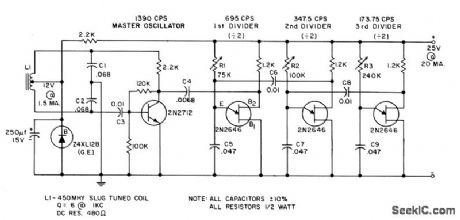
Class C Hartley master oscillator serves for synchronizing three basic relaxation oscillators that would otherwise be free-running. Dividers remain locked over temperature range of 0 to 70℃.- Transistor Manual, Seventh Edition, General Electric Co., 1964, p 342. (View)
View full Circuit Diagram | Comments | Reading(1693)
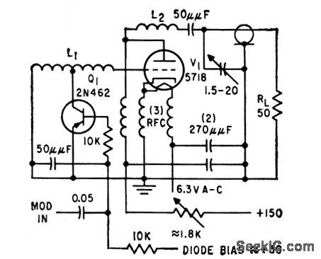
100_MC_VRAICAP_OSCILLATOR
Published:2009/7/14 22:40:00 Author:Jessie
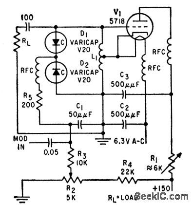
Modulator consists of two variable-capacitance diodes in series to r-f and in parallel to audio modulating signals and d-c bias. Frequency deviation is 28 Mc peak-to-peak with modulating signals less thon 28 v and negligible modulating power.-C. Arsem, Wideband F-M with Capacitance Diodes, Electronics, 32:49, p 112-113. (View)
View full Circuit Diagram | Comments | Reading(818)
1_MC_F_M_OSCILLATOR
Published:2009/7/14 22:38:00 Author:Jessie
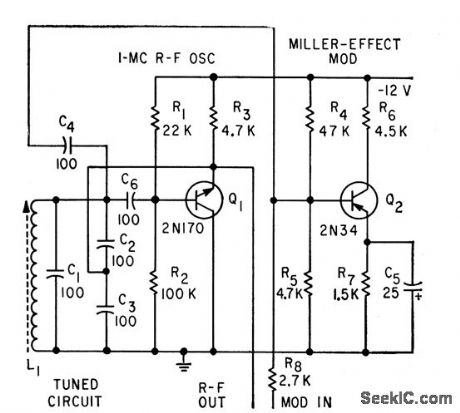
Combines Q multiplier with Miller effect to produce simple and stable f-m oscillator and modulator.-P. W. Wood, Transistorized F-M Oscillator, Electronics, 32:5, p 64. (View)
View full Circuit Diagram | Comments | Reading(1033)
STRAIN_GAGE_OSCILLATOR
Published:2009/7/14 23:26:00 Author:Jessie
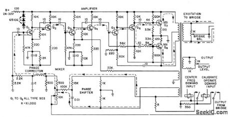


Produces f-m signal output that is directly proportional to applied force, such as stress or pressure resistive-type gage. Operating and band, edge frequencies of oscillator are determined by values of R, L, and C.-W. H. Foster, Strain Gage Oscillator for Flight Testing, Electronics, 31:5, p 40-42. (View)
View full Circuit Diagram | Comments | Reading(866)
QUADRATURE_OSCILLATOR_USES_MULTI
Published:2009/7/14 20:48:00 Author:May
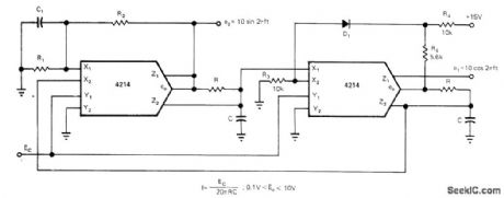
PLIERS-4214 differential multipliers eliminate need for opamps in quadrature oscillator in which frequency is controlled by external DC voltage. R3, R4, R5, and D1 form diode limiter, while R1,R2,and C1,provide positive feedback to sustain oscillation,R1 should be about equal to R, R2about 20R, and C1 about 10C. R2 can be readjusted for best compromise between distortion and speed of amplitude buildup.-Y. J. Wong, Design a Low Cost, Low-Distortion, Precision Sine-Wave Oscillator, EDN Magazine, Sept. 20, 1978, p 107-113. (View)
View full Circuit Diagram | Comments | Reading(1124)
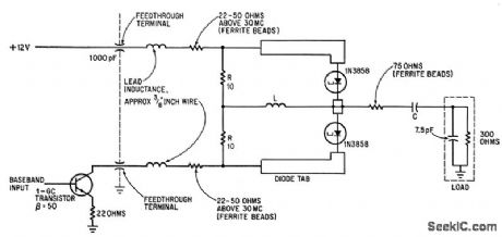
400_MC_VARICAP_OSCILLATOR
Published:2009/7/14 23:24:00 Author:Jessie
Wideband frequency modulation of 400-Mc distributed-parameter Colpitts oscillator is obtained with symmetrical transistor in modulator. Q1 is equivalent to two reverse, biased diodes in series for r-f and in parallel with respect to modulating signals and d-c bias.-C. Arsem, Wideband r-m with Capacitance Diodes, Electronics, 32:49, p 112-113. (View)
View full Circuit Diagram | Comments | Reading(968)
ELECTRIC_TUNING_FOR_F_M_OSCILLATOR
Published:2009/7/14 23:23:00 Author:Jessie
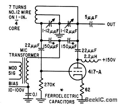
Voltage-tunable ferroelectric capacitors are used for tuning as well as for modulating.-T. W. Butler, Jr., Ferroelectrics Tune Electronic Circuits, Electronics, 32;3, p 52-55. (View)
View full Circuit Diagram | Comments | Reading(772)
VOLTAGE_CONTROLLED_100_MC_OSCILLATOR
Published:2009/7/14 23:06:00 Author:Jessie
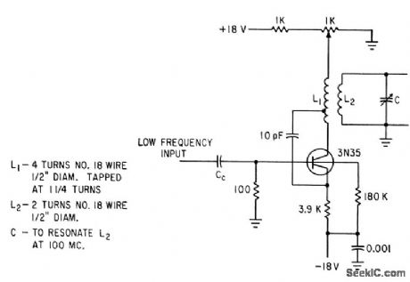
Video voltage of wide-band f-m receiver is applied to base of silicon tetrode to give voltage-sensitive 100-Mc f-m oscillator in which deviations can be up to 1 Mc without excessive distortion.-S. Kallus, B. Robinovici, and A. Newton, Fitting a Wide.Band Signal Into a Narrow-Band Receiver, Electronics, 36;10, p 47-49. (View)
View full Circuit Diagram | Comments | Reading(881)
CONTROL_FOR_VOLTAGE_TUNED_OSCILLATOR
Published:2009/7/14 20:39:00 Author:May
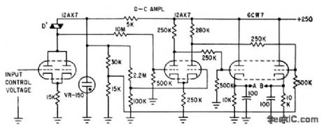
Input d-c control voltage required by SiC varistors of voltage-tuned oscillator is boosted by d-c amplifier stages that produce two control voltages (at A and B) for SiC varistors of phase-shift oscillator circuit, changing their a-c resistance and thereby oscillator frequency.-M. Uno, Varistor Network Controls Voltage-Tuned Oscillator, Electronics, 34:30, p 44-47. (View)
View full Circuit Diagram | Comments | Reading(1025)
VARACTOR_MODULATES_24_MC_F_M_OSCILLATOR
Published:2009/7/14 22:53:00 Author:Jessie
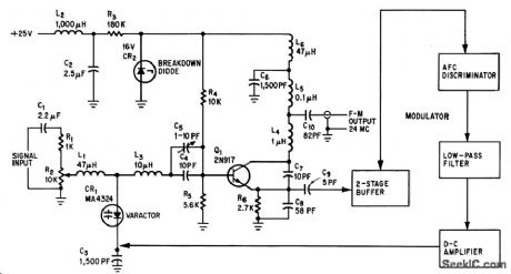
Modulating signal is applied to vat deviation of 60 kc.-N. Downs and B. varactor diode in frequency-determining circuit of telemetering oscillator. Linearity is 2% for deviation of 60 kc.-N. Downs and B. van Sutphin, Solid-State Transmitter Ready for UHF Telemetry, Electronics, 37:17, p 76-80. (View)
View full Circuit Diagram | Comments | Reading(836)
200_MC_VOLTAGE_CONTROLLED_OSCILLATOR
Published:2009/7/14 22:50:00 Author:Jessie
Uses two tunnel-diodes in astable mvbr to give symmetrical square wave output. Used to produce wide frequency swing with respect to center frequency, linearly, when small control voltage is applied.-F. H. Lefrak, Tunnel-Diode Oscillator Expands F.M System's Tunnel-Diode Oscillator Expands F-M System's Channel Capacity, Electronics ,39:1, P 105-109. (View)
View full Circuit Diagram | Comments | Reading(906)
VOLTAGE_CONTROLLED_CRYSTAL
Published:2009/7/14 20:33:00 Author:May
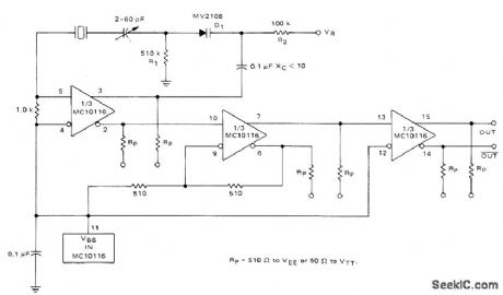
Voltage-variable capacitance tuning diode in series with crystal feedback path of Motorola MC10116 IC gives frequency deviation of about ±50 PPM for 1-MHz crystal when using tuning voltage range of 0-25 VDC. Deviation is greater at higher crystal frequencies.-B. Blood, IC Crystal Con-trolled Oscillators, Motorola, Phoenix, AZ, 1977, AN-417B, p 6.
(View)
View full Circuit Diagram | Comments | Reading(1733)
AVC_AND_VOX
Published:2009/7/14 7:59:00 Author:May
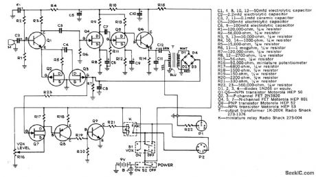
Voice-operated ON/OFF switch uses microphone to sense normal back-ground sound. Anything above background threshold preset by R16 energizes relay K for turning on recorder. Circuit provides about 2-s delay after subject stops talking, before releasing relay. Automatic volume control circuit keeps recorded signal essentially constant despite movements of loudspeaker toward or away from microphone.-G. Beard, Automatic Volume and VOX for Your Tape Recorder, Popular Science, Oct. 1973, p 134 and 136. (View)
View full Circuit Diagram | Comments | Reading(1513)
ERASE_BIAS_OSCILLATOR
Published:2009/7/14 5:09:00 Author:May
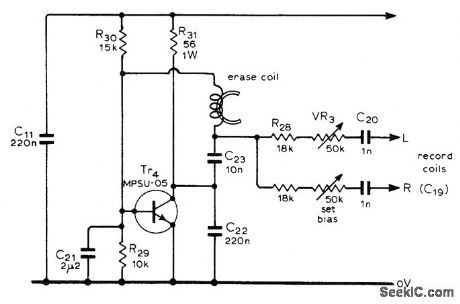
Used in high-quality stereo cassette deck operating from AC line or battery. Provides up to 33 VRMS at 50-kHz erase frequency, as required for completely erasing existing recording on tape when recording over it. Supply voltage should be in range of 12-14 V. Article gives all other circuits of cassette deck and describes operation in detail.- J. L. Linsley Hood, Low-Noise, Low-Cost Cassette Deck, Wireless World, Part 1-May 1976, p 36-40 (Part 2-June 1976, p 62-66; Part 3-Aug. 1976, p 55-56) (View)
View full Circuit Diagram | Comments | Reading(3909)
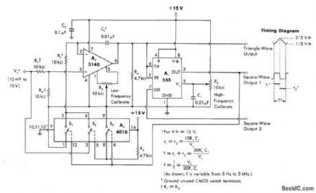
EXPON_ENTIAL_VCO
Published:2009/7/14 4:58:00 Author:May
Can be driven with linear time base of voltage and used with logarithmic frequency display, as in frequency-response tests Useful range of circuit is four decades Values shown give timing-current range of 10 nA to 100 μA, yielding frequency range of 1 Hz to 10 kHz. Input voltage range of 60 mV per decade is obtained from voltage divider R1-R2 to allow higher and more practical value for actual input voltage to circuit. –W. G. Jung, IC Timer Cookbook, Howard W. Sams, Indianapolis, IN, 1977, p 174-179. (View)
View full Circuit Diagram | Comments | Reading(1191)
1_kHz_VCO
Published:2009/7/14 4:56:00 Author:May
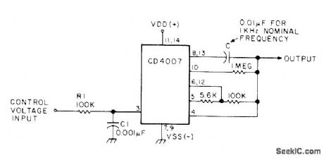
Changes in control voltage input are used to vary nominal 1-kHz output of CD4007 CMOS voltage-controlled oscillator proportionately. Values of R and C can be changed to obtain other nominal frequencies.-W. J. Prudhomme, CM0S Oscillators, 73 Magazine, July 1977, p 60-63.
(View)
View full Circuit Diagram | Comments | Reading(2631)
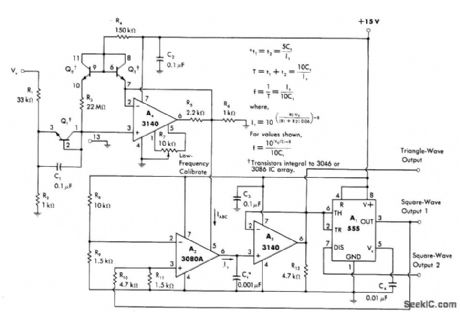
LINEAR_VCO_1
Published:2009/7/14 4:44:00 Author:May
Operates over control-voltage range of +10 mV to +10 V to provide either square or triangle outputs from 5 Hz to 5 kHz, Can be used for instrumentation or electronic music applications.- W. G. Jung, IC Timer Cookbook, Howard W. Sams, Indianapolis, IN, 1977, p 174-179.
(View)
View full Circuit Diagram | Comments | Reading(1069)
| Pages:18/54 1234567891011121314151617181920Under 20 |
Circuit Categories
power supply circuit
Amplifier Circuit
Basic Circuit
LED and Light Circuit
Sensor Circuit
Signal Processing
Electrical Equipment Circuit
Control Circuit
Remote Control Circuit
A/D-D/A Converter Circuit
Audio Circuit
Measuring and Test Circuit
Communication Circuit
Computer-Related Circuit
555 Circuit
Automotive Circuit
Repairing Circuit