
Oscillator Circuit
Index 19
LINEAR_VCO
Published:2009/7/14 4:40:00 Author:May
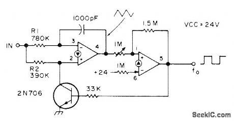
Two sections of LM3900 quad linear opamp provide linear response for inputs of 2-12 VDC, Circuit can be adjusted with 1-megohm pot so 4-V input produces 400-Hz square wave at output, 5 V gives 500 Hz, etc. First opamp is connected as integrator and second as Schmitt trigger. When Schmitt output is high, transistor is turned on and diverts current away from noninverting input so integrator output ramps down toward ground.-C. Sondgeroth, More PLL Magic, 73 Magazine, Aug. 1976, p 56-59. (View)
View full Circuit Diagram | Comments | Reading(0)
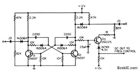
COLLECTOR_VOLTAGE_CONTROL_AFC_OSCILLATOR
Published:2009/7/15 3:36:00 Author:Jessie
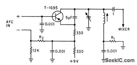
Afc input signal acts through series resistor to vary collector voltage of 40.Mc oscillator. Sensitivity is 2.5 Mc per V. Bias network adjustment is critical.-T. P. Prouty, Using Varactors to Extend Frequency-Control Range, Electronics, 36:45, p 48-49. (View)
View full Circuit Diagram | Comments | Reading(737)
VARACTOR_CONTROLLED_40_MC_OSCILLATOR_
Published:2009/7/15 3:35:00 Author:Jessie
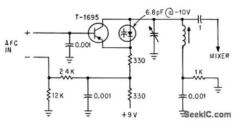
Oscillator transistor also acts as a d-c amplifier between afc input and varactor diode to give electronic tuning over range of 11 Mc with sensitivity of 5.8 Mc per v.-T. P. Prouty, Using Varactors to Extend Frequency-Control Range, Electronics, 36:45, p 48-49. (View)
View full Circuit Diagram | Comments | Reading(811)
EMITIER_CURRENT_CONTROL_40_MC_AFC_OSCILLATOR
Published:2009/7/15 3:34:00 Author:Jessie
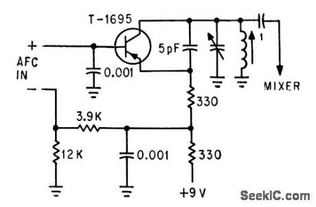
Error signal, usually derived from external discriminator, is applied in series with base bias network to give sensitivity of about 1.5 Mc per v and nearly straight voltage-frequency characteristic.-T. P. Prouty, Using Varactors to Extend Frequency-Control Range, Electronics,36:45, p 48-49. (View)
View full Circuit Diagram | Comments | Reading(816)
TRIGGERED_BLOCKING_OSCILATOR
Published:2009/7/14 4:20:00 Author:May
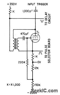
Gives pair of output pulses, with opposite polarity, for controlling timing and spacing of flashes.-P. Scott, Microflash and Pulse Stimulator Tests Human Optical Response, Electronics, 34:27, p 48-51. (View)
View full Circuit Diagram | Comments | Reading(868)
HYSTERESIS_AND_DELAY_OSCILLATOR
Published:2009/7/15 4:59:00 Author:Jessie
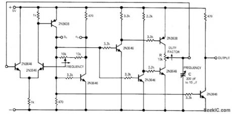
Separate noninteracting frequency and duty-factor controls permit construction of simple telemetry oscillators having inherently linear transfer function. Absolute synchronization of independent and dependent variables is obtainable with relatively simple pulse-generating circuits. Synchronization cannot be lost. Average value of threshold voltage is maintained constant. Adjustment of hysteresis gap width moves threshold voltage limits symmetrically about average value. Resistance portion of RC delay is switched from positive to negative voltage symmetrically also. Article covers circuit operation in detail.-W. H. Swain, True Digital Synchronizer Employs Hysteresis-and-Delay Element, EDN Magazine, Jan. 1, 1971, p 33-35. (View)
View full Circuit Diagram | Comments | Reading(975)
CURRENT_CONTROLLED_OSCILLATOR
Published:2009/7/14 4:06:00 Author:May
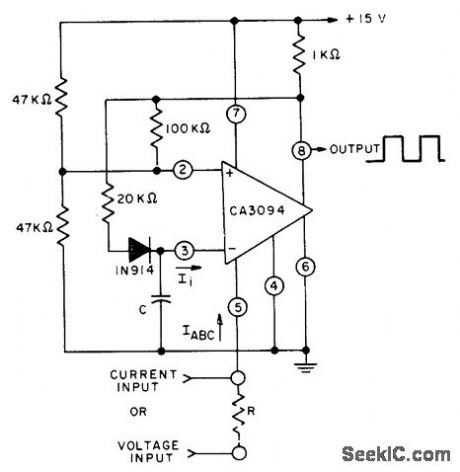
Makes use of proportional relationship between input current li and amplifier input bias current lABC of CA3094 programmable opamp. Linearity is within 1% over middle half of characteristic. Circuit can be used for voltage input if voltage is applied to pin 5 through appropriate dropping resistor R. Output is square wave. - Circuit Ideas for RCA Linear ICs, RCA Solid State Division, Somerville, NJ, 1977, p4. (View)
View full Circuit Diagram | Comments | Reading(1120)
21_2125_MHz_with_VFO
Published:2009/7/14 3:50:00 Author:May
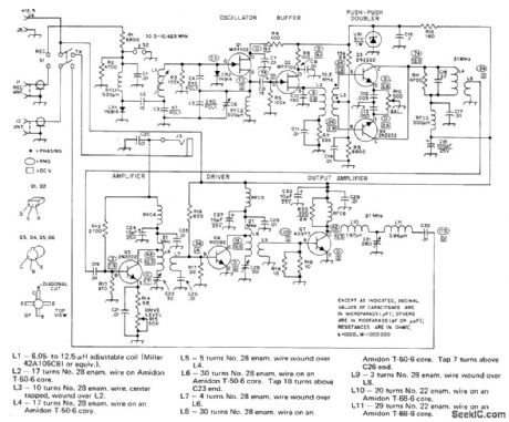
Developed for low-power CW work in 15-meter amateur band. Colpitts oscillator Q1 runs continuously at 10.5-10.625 MHz during transmit and receive, for good frequency stability, so VF0 frequency must be shifted away from operating frequency during receive periods. Supply is 12 V at 1.3 A. C6 is 4-53.5 pF. RFC4 is 16turns No. 28 enamel, RFC5 is 11 turns No. 22, and RFC6 is 6 turns No. 22, each on Amidon FT-50-61 core. Article covers construction and tune-up.-J. Rusgrove, A 15-Meter Goober Whistle, QST, Jan. 1976, p 16-19. (View)
View full Circuit Diagram | Comments | Reading(1018)
80_METER_VFO
Published:2009/7/14 3:42:00 Author:May
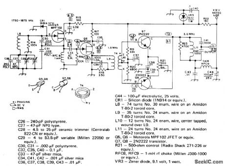
Used in place of crystal-con- trolled oscillator in low-power (QRP) amateur -transmitter. Tuning range is 1750-1875 kHz in 160-meter band. Colpitts oscillator uses JFET Q5 with series-tuned tank for good stability. Q6 provides isolation between oscillator and push-push class C doubler amplifier stage. Doubling gives desired 80-meter output.-D. DeMaw and J. Rusgrove, Learning to Work with Semicon-ductors, QST, Oct. 1975, p 38-42. (View)
View full Circuit Diagram | Comments | Reading(2443)
VOLTAGE_CONTROLLED_0_1_KC_OSCILLATOR__
Published:2009/7/15 20:51:00 Author:Jessie
Pulse-counting discriminator in feedback loop gives adequate linearity for computing applications. As input voltage rises from 0 to 10 mV, oscillator output frequency rises proportionally.-N. W. Bell and V. Chiunti, Voltage-Controlled Oscillator Uses Negative Feedback,Electronics.35:11,p65-65. (View)
View full Circuit Diagram | Comments | Reading(921)
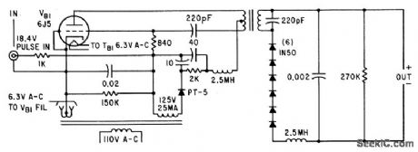
INDUCTION_HEATER_POWER_OSCILLATOR
Published:2009/7/14 3:30:00 Author:May
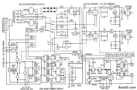
Circuit includes power supplies for oscillator and keyer bias.-R. E. Mathews and F. R.Sias, Jr., Testing Space Craft with Induction Heaters, Electronics, 35:34. P,38-41. (View)
View full Circuit Diagram | Comments | Reading(3152)
ISOLATION_OSCILLATOR
Published:2009/7/14 3:25:00 Author:May
Used to isolate duty-cycle generator induction heater control system from pulser of power oscillator.-R.E.Mathews and F. R. Siad, Jr., Testing Space Craft with Induction Heaters,Electronics,35:34,p 38-41. (View)
View full Circuit Diagram | Comments | Reading(973)
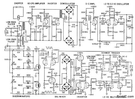
DIFFERENTIAL_D_C_AMPLIFIER_CONTROLS_23O_KC_C_W_RADAR_OSCILLATOR
Published:2009/7/15 5:06:00 Author:Jessie
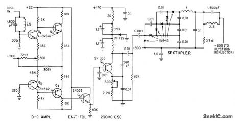
Combined output of two detectors in dual-mode cavity, having typical discriminator S curve, is amp lified by four transistors in differential d-c circuit and applied to oscillator through emitter-follower to make output voltage swing up to 20%. Voltage sextupler applies step-up voltage to reflector of klystron, to maintain klystron frequency constant within 0.2 Mc.-H. D. Raynes, C-W Radar Measures Artillery Ballistics, Electronics, 37:1, p 31-33. (View)
View full Circuit Diagram | Comments | Reading(934)
TV_HORIZONTAL_SWEEP_OSCILLATOR
Published:2009/7/15 5:05:00 Author:Jessie
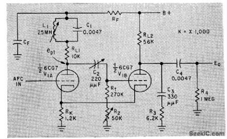
Cathode-couped multivibrator includes noise-immunizing tuned circuit in plate circuit of 'triode.-C. L. Barsony, Graphical Checkout of Multivibrator Design, Electronics, 33:8, p 55-57. (View)
View full Circuit Diagram | Comments | Reading(1274)
GATE_OPENING_100_KC_OSCILLATOR
Published:2009/7/15 21:50:00 Author:Jessie
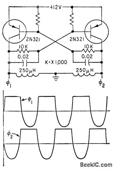
Output voltages are taken across r-f chokes in collector circuits, for controlling number gates of crt display that creates handwritten numerals.-R L. White. Forming Handwritten like Digits on CRT display. Electronics,32:11,p138-140. (View)
View full Circuit Diagram | Comments | Reading(1066)
RING_TYPE_OSCILLATOR
Published:2009/7/15 23:47:00 Author:Jessie
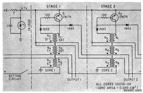
After core-setting current is removed, pulse output of Q1 is followed by output of Q2 after delay of 100 microsec to 3 sec, depending primarily on input voltage and core size. No separate drive oscillator is required when used as ring counter.-J. M. Marzolf, Magnelic-Core Ring Counter Needs No Drive, Electronics, 35:12, p 52-53. (View)
View full Circuit Diagram | Comments | Reading(1082)
WARBLE_TONE_OSCILLATOR
Published:2009/7/13 23:13:00 Author:May
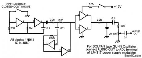
Originally used for microwave transmitter testing, this warble oscillator produces a tone that jumps between two frequencies. (View)
View full Circuit Diagram | Comments | Reading(1266)
7_71_MHz_VFO
Published:2009/7/13 22:51:00 Author:May
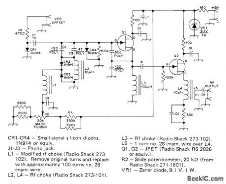
JFET Q1 serves as oscillator, with frequency determined by C2, L2, CR2, and CR3; diodes operate in reverse-bias regions as voltage-variable capacitors. Amount of reverse bias applied by R2 determines capacitance and frequency. VFO operates on both transmit and receive; on transmit, no voltage is applied to VFO offset circuit R1-C1-CR1 so it has little effect on oscillator, 0n receive, +12 V applied to R1 makes CR1 conduct and places C1 across frequency-determining network to shift VFO about 100 kHz away from operating frequency so receiver will not be blocked. Q2 is buffer between oscillator and transmitter. VR1 provides regulated 9.1 V for oscillator and buffer. (Project was named after chopped beef can in which it was mounted.)-J. Rusgrove, The CB Slider, OST, March 1977, p 15-17. (View)
View full Circuit Diagram | Comments | Reading(1318)
4224_MHz_CRYSTAL_OSCILLATOR
Published:2009/7/13 22:05:00 Author:May
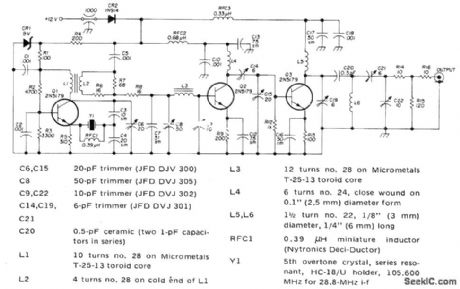
Uses 105.6-MHz crystal oscillator followed by frequency-doubling stages to give desired output for driving external diode-type tripler for which circuit is also given in article, Developed for use in 1296-MHz SSB transceiver for 23-cm amateur band.-H. P. Shuch, Easy-to-Build SSB Transceiver for 1296 MHz, Ham Radio, Sept. 1974, p 8-23. (View)
View full Circuit Diagram | Comments | Reading(1993)
6545_6845_MHz_VFO
Published:2009/7/13 22:03:00 Author:May
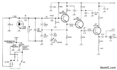
Covers 40-meter amateur band of transceiver for SSB and CW with stable incremental tuning circuit using Motorola MV1654 varactor diode CR3. Tuner permits up to 10-kHz offset above or below VFO frequency. Varactor control voltage is set by offset tuning control R3. R4 compensates for differences in varactors and adjusts VFO for zero off-set. Output buffering is provided by Q6 and Q7, with 07 also serving as power amplifier for balanced mixer used in companion exciter of transmitter. S2 activates receiver offset. Relay K1 automatically turns off offset when receiver is in transmit or standby mode, Offset feature is needed only if there is frequency difference between transmitted and received signals. L4 has 5 turns No. 22 on 1/2-inch slug-tuned ceramic form.-W. J. Weiser, Simple SSB Transmitter and Receiver for 40 Meters, Ham Radio, March 1974, p 6-20. (View)
View full Circuit Diagram | Comments | Reading(2249)
| Pages:19/54 1234567891011121314151617181920Under 20 |
Circuit Categories
power supply circuit
Amplifier Circuit
Basic Circuit
LED and Light Circuit
Sensor Circuit
Signal Processing
Electrical Equipment Circuit
Control Circuit
Remote Control Circuit
A/D-D/A Converter Circuit
Audio Circuit
Measuring and Test Circuit
Communication Circuit
Computer-Related Circuit
555 Circuit
Automotive Circuit
Repairing Circuit