
Amplifier Circuit
Index 221
Accurate measuring amplifier circuit diagram
Published:2011/5/17 1:35:00 Author:Ecco | Keyword: Accurate , measuring , amplifier
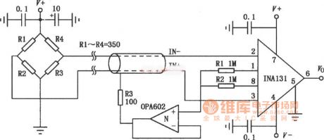
INA131 is a low-cost general-purpose amplifier, the internal gain resistance corrected by the laser will make the gain error be small, it can provide the standard gain with 100 times by itself. High precision measuring amplifier is shown as Figure, the input signal is from the electrical bridge sensor (such as strain load cell, displacement measurement sensors, etc.). This connection has high interference suppression to the 50Hz power interference and high common-mode interference. If magnification is 100, it needs a higher gain, it should be increased a gain resistor RG between ①, ⑧ foot, the gain size is: G = 100 +250 kΩ / RG. (View)
View full Circuit Diagram | Comments | Reading(589)
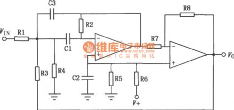
Broadband amp circuit
Published:2011/5/16 7:57:00 Author:Christina | Keyword: Broadband, amp circuit
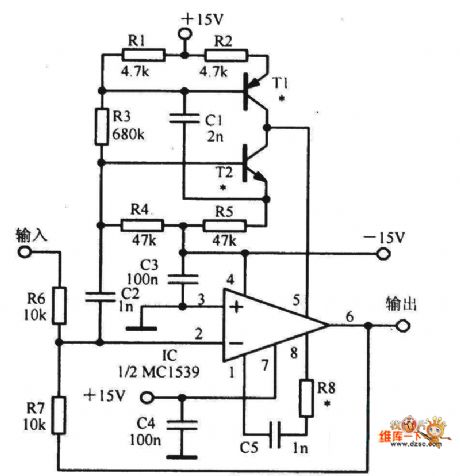
The Broadband amp circuit is as shown:
(View)
View full Circuit Diagram | Comments | Reading(606)
Resistance Bridge Amplification Circuit Composed Of INA155
Published:2011/5/16 22:27:00 Author:Robert | Keyword: Resistance, Bridge, Amplificatio
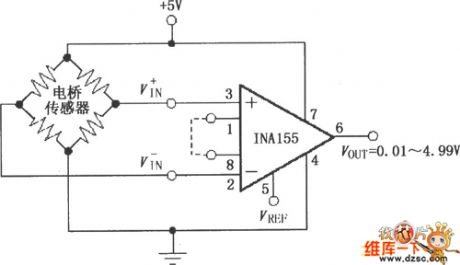
The Resistance Bridge Amplification Circuit Composed Of INA155 is shown in the picture below.
(View)
View full Circuit Diagram | Comments | Reading(852)
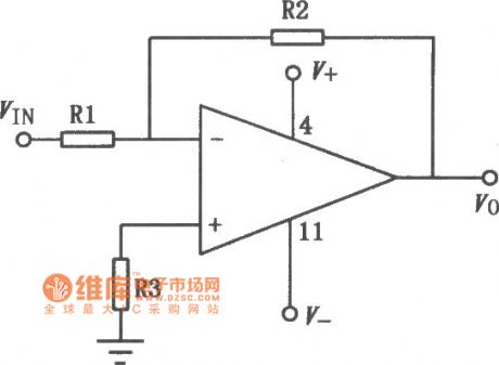
FET Transistor Operational Amplifier Circuit
Published:2011/5/17 1:41:00 Author:Robert | Keyword: FET Transistor, Operational Amplifier
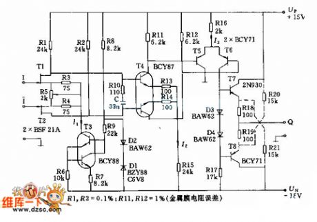
The FET Transistor Operational Amplifier Circuit is shown below.
(View)
View full Circuit Diagram | Comments | Reading(894)
BA3304F-the integrated circuit of 2-channel audio preamplifiers
Published:2011/5/15 5:38:00 Author:Borg | Keyword: integrated circuit, 2-channel, audio preamplifiers
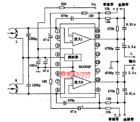

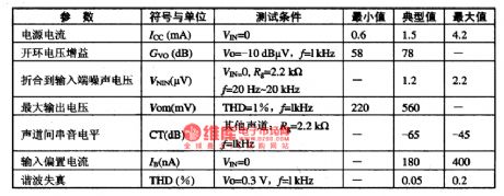
BA3304F is an integrated circuit of 2-channel audio preamplifiers produced by Toyo Power Tool Corp., Japan, which is used in miniature stereo players.1.the internal circuit and pin functions of BA3304FBA3304F consists of two teams of sub-circuits of preamplifiers and frequecy compensation, and filters, etc. Figure 1 is the internal circuit and typical application circuit. And the IC is in flat 16-lead dual line packages, whose pin functions and data are listed in Table 1.
2.main parameters of BA3304F
(View)
View full Circuit Diagram | Comments | Reading(963)
Operational amplifier universal CNC offset adjustment circuit diagram
Published:2011/5/12 4:22:00 Author:Rebekka | Keyword: Operational amplifier, universal CNC , offset adjustment
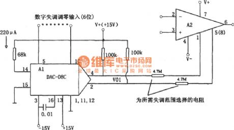
Figure shows the operational amplifier universal CNC offset adjustment circuit. The imbalance change uses digital control. The integrated chip DAC-08C is used as the six D / A converter. ②, ④ are output pins, they externally connect with two l00kΩ resistors. These 2 resistor is equivalent to load resistance. It generates output voltage Vo1. The output voltage Vo1. It passes the two 4.7MΩ large resistors and turns to the A2 offset adjusting current. The two 4.7MΩ large resistors are set by the range of disorders. The circuit is useful to the big circuit system. Because virtually any offset voltage can be stored in the memory, you can add it to the the amplifier when it is necessary. (View)
View full Circuit Diagram | Comments | Reading(906)
Simple differential amplifier circuit diagram composed of μA709
Published:2011/5/13 3:06:00 Author:Rebekka | Keyword: Simple differential amplifier
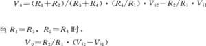
Simple differential amplifier circuit is shown as above. Two input signals Vi1 and Vi2 are added to the input terminal after passing the R1 and R3, R4 divide voltage circuit. Vi1 is added to the inverting input of the op amp, Vi2 is added to the same input terminal. The relationship of the output voltage Vo and Vi1, Vi2 are shown as above.
The output voltage is R2/R1 times of the difference between the two signals. It can get a different output voltage by proper selection of the ratio of R2/R1. (View)
View full Circuit Diagram | Comments | Reading(1638)
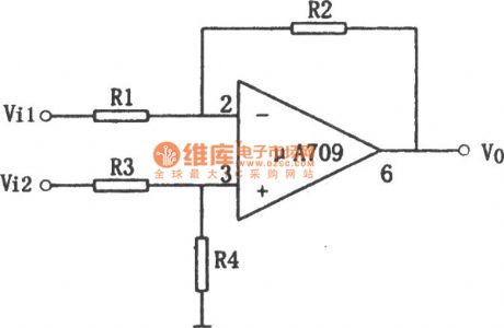
μA741 dual power universal single op amp circuit diagram
Published:2011/5/13 2:47:00 Author:Rebekka | Keyword: dual power, universal single op amp
μA741 is a high performance, internal compensation operational amplifier. The features are: Low power consumption, no external frequency compensation. It is with offset voltage short circuit protection and offset voltage zeroing capacity. It will not appear latch phenomenon when it is working. It can be used as integrator, summing amplifier and general feedback amplifier. The similar or direct substitution models are: CF741MT, CF741CT, CF741MD, CF741CD, CF741MJ, CF741CJ, CF741CP, F007, F008 and so on. The μA741 typical application circuit is shown as above. Figure (a) is the inverting input amplifier circuit, Figure (b) is the same phase input amplifier circuit. (View)
View full Circuit Diagram | Comments | Reading(1078)
CF7631 series dual power high input impedance three op amp circuit diagram
Published:2011/5/13 4:21:00 Author:Rebekka | Keyword: dual power high input, impedance three op amp
CF7631 is a CMOS low-power three-op amp. The features are: High input resistance, small input current, low power consumption, high gain. It is with frequency compensation, non-zero offset end, peripheral bias control. Its working voltage is ± 0. 5V ~ ± 8V. Its similar or direct substitution models are: CF7631BMD, CF7631BCD, CF7631CMD, CF76321CCD, CF7631ECD, CF7631BMJ, CF7631BCJ, CF7631CMJ, CF7631CCJ, CF7631ECJ, CF7631BCP, CF7631CCP, CF76321ECP and so on. The typical application circuit is shown as above. (View)
View full Circuit Diagram | Comments | Reading(607)
CM358 single power supply universal dual op amp circuit diagram
Published:2011/5/13 4:15:00 Author:Rebekka | Keyword: single power supply, universal dual op amp
CM358 is a high gain, contains two operational amplifier unit amplifiers. It is with no external frequency compensation. It only uses a single power supply and it has a low input current. It is usually used for transducer amplifier, the DC gain units and common signal processing circuit. Its similar or direct substitution models are: CFl58MT, CF258LT, CFl58MD, CF358CT, CF258LD, CF358CD, CFl58MJ, CF258LJ, CF358CJ, CF358CP, LM158 and so on. The typical application circuit is shown as above. (View)
View full Circuit Diagram | Comments | Reading(1092)
CF148 series dual power universal quad op amp circuit diagram
Published:2011/5/13 4:37:00 Author:Rebekka | Keyword: dual power universal, Quad op amp
CF148 series include four high-performance amplifier units. Each unit's performance is similar with gA741 op amp. It is with high gain, internal compensation, low power consumption, 4 op amp quiescent current phases are similar with μA741. This series uses internal accurate isolation technology. It is suitable for the occasions that requires multiple μA741. The similar or direct substitution models are: CFl48MD, CF248LD, CF348CD, CFl48MJ, CF248LJ, CF348CJ, CF348CP and so on. The typical application circuit is shown as above.
(View)
View full Circuit Diagram | Comments | Reading(606)
3583 op-amp circuit
Published:2011/5/16 4:20:00 Author:Christina | Keyword: op-amp
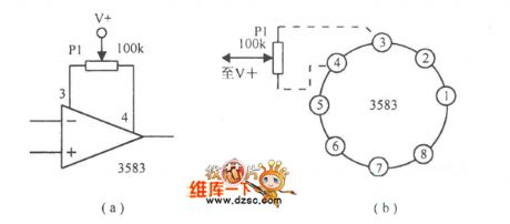
The 3583 op-amp circuit is as shown:
(View)
View full Circuit Diagram | Comments | Reading(577)
operational amplifier symbol and power connection circuit
Published:2011/5/16 3:38:00 Author:Christina | Keyword: operational amplifier, symbol, power connection
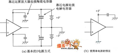
The operational amplifier symbol and power connection circuit is as shown:
(View)
View full Circuit Diagram | Comments | Reading(682)
Automatic weighing and measuring instrument circuit
Published:2011/5/16 3:28:00 Author:Christina | Keyword: Automatic, weighing, measuring, instrument circuit

View full Circuit Diagram | Comments | Reading(684)
Simulation mechanical system circuit
Published:2011/5/16 3:17:00 Author:Christina | Keyword: Simulation, mechanical system
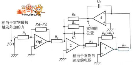
The Simulation mechanical system circuit is as shown:
(View)
View full Circuit Diagram | Comments | Reading(624)
BA3570F-the integrated drive circuit of low-voltage headphone
Published:2011/5/14 8:00:00 Author:Borg | Keyword: drive circuit, low-voltage headphone
BA3570F is the integrated drive circuit of low-voltage headphone produced by Toyo Power Tool Corp.,Japan, which is widely used in walk-man.1.the typical application circuit of BA3570FThe typical application circuit of BA3570F is as shown in Figure 1, which characterizes with a Auto-matic Loudness Control System, i.e ALS.
2.the main parameters of BA3570FThe working power supply voltage of BA3570F ranges 2-7.2V, typical working voltages are 3V and 6V. When Vcc=3V,THD=1O% and RL=16Ω, the typical output power is Po=3OmWX2。3.pin functionsof BA3570FBA3570 is in flat 22-lead dual line package.
(View)
View full Circuit Diagram | Comments | Reading(1248)
600MHz broadband amplifier circuit
Published:2011/5/16 2:51:00 Author:Christina | Keyword: 600MHz, broadband amplifier
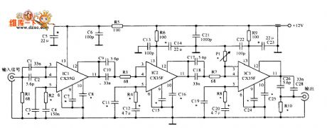
The 600MHz broadband amplifier circuit is as shown:
(View)
View full Circuit Diagram | Comments | Reading(605)
CXD3068-the integrated circuit of digital signal processing and digital servo processing
Published:2011/5/14 7:41:00 Author:Borg | Keyword: integrated circuit, digital signal processing
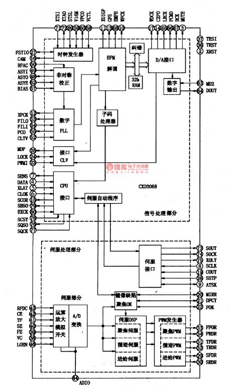
CXD3068 is an integrated circuit of digital signal processing and digital servo processing, which is produced by SONY Corp.,Japan on the basis of CXD3008 chips. The chip is widely used in all kinds of disc players.1.Function featuresThe digital processing of CXD3068 is done by 32KBRAM which combines the digital lock-phase technology and the super error-correcting algorithm, and the circuit can do EFM demodulation to the input AF signal; the digital servo circuit is under the control of microprocessors, besides, it has 6-level recurring filter and 5-level focusing filter.
(View)
View full Circuit Diagram | Comments | Reading(907)
BA4402-The FM high-frequency integrated circuit
Published:2011/5/14 2:47:00 Author:Borg | Keyword: FM, high-frequency
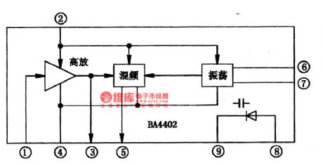
BA4402 is a FM high frequency integrated circuit produced by Toyo Corp.,Japan, which is used in radio circuit of all kinds of stereos as the high-frequency circuit.1.the internal circuit of BA4402BA4402 contains FM amplifier,frequency mixing, local oscillator and AFC variable-capacitance diode, which characterizes with wide voltage range and large gain.BA4402 is in 9-lead single in-line package, whose internal circuit is as shown in Figure 1, while pin functions and data are listed in Table 1.
(View)
View full Circuit Diagram | Comments | Reading(2300)
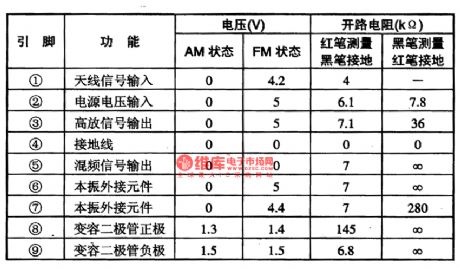
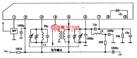
BA4230AFS-The AM electrical tuning and FM middle amplifier integrated circuit
Published:2011/5/14 3:11:00 Author:Borg | Keyword: tuning, AM, FM
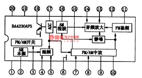
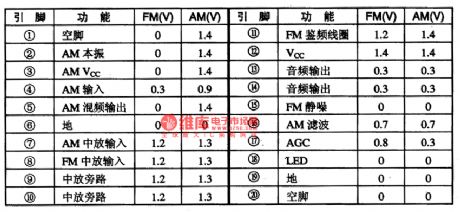
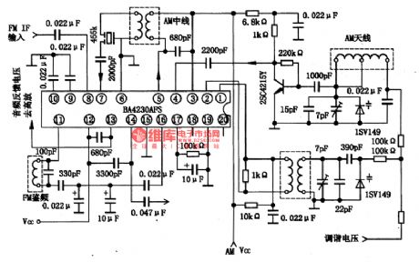
BA4230AFSis an AM electrical tuning and FM middle amplifier integrated circuit produced by Toyo Corp.,Japan, which is used in micro AM/FM radios of assembly 1.5V power supply.the internal circuit and pin functions of BA4402The FM part of BA423OAFS contains difference IF amplifier, double balance wave-detector, IF silence-noise circuit. The AM part contains local oscillator, frequency mixing,middle amplifier, wave detection and AGC circuit. Besides, BA423OAFS contains tuning indicating LED drive circuit. The internal circuit of the chips are shown in Figure 1.
(View)
View full Circuit Diagram | Comments | Reading(1142)
| Pages:221/250 At 20221222223224225226227228229230231232233234235236237238239240Under 20 |
Circuit Categories
power supply circuit
Amplifier Circuit
Basic Circuit
LED and Light Circuit
Sensor Circuit
Signal Processing
Electrical Equipment Circuit
Control Circuit
Remote Control Circuit
A/D-D/A Converter Circuit
Audio Circuit
Measuring and Test Circuit
Communication Circuit
Computer-Related Circuit
555 Circuit
Automotive Circuit
Repairing Circuit