
Control Circuit
Index 193
Simple infrared ray control lighting switch circuit
Published:2011/7/25 20:20:00 Author:Christina | Keyword: Simple, infrared ray, control, lighting switch
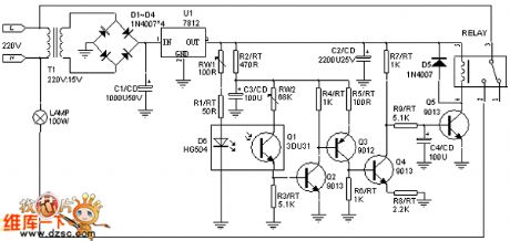
When you connect the power supply, the infrared emitting diode d6 sends out the infrared ray, and the phototransistor q1's c-e pole is in the low resistance state under the infrared light irradiation, and the q2's base electrode b is in the high level state, q2 conducts. Then q3 and q4 conduct. q5's base electrode b has the low level and is in the cut-off state because the q4 is conducted, the relay will not operate. When the person or object cuts off the infrared beam of d6, the q1's c-e pole is in the high level state, then q2, q3, q4 cut off, q5 conducts, the relay operates to turn on the light.
(View)
View full Circuit Diagram | Comments | Reading(1272)
Electric fence control circuit 8
Published:2011/7/25 2:35:00 Author:Ecco | Keyword: Electric fence control
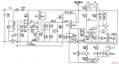
The electric fence control circuit is composed of the power supply circuit, self-oscillating circuit, trigger control circuit, high voltage circuit and alarm circuit, and it is shown in Figure 4-33. Power supply circuit is composed of the battery GB, power switch Sl, voltmeter PV, ammeter PA, filter capacitor Cl, inductor L and isolation diode VDg. Self-oscillation circuit is composed of the electronic switch integrated circuit ICl, resistors Rl-R5, R8, R9, capacitors C2-C4, potentiometer RPl, diodes VDl, VD2 and oscillation transformer Tl.
(View)
View full Circuit Diagram | Comments | Reading(4723)
Electric fence control circuit 9
Published:2011/7/25 2:32:00 Author:Ecco | Keyword: Electric fence control
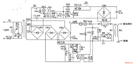
The electric fence control circuit is composed of the power supply circuit, trigger control circuit, high voltage circuit and alarm circuit, and it is shown in Figure 4-34. Power supply circuit is composed of the power switch Sl, voltmeter PV, fuse FU, resistors Rl, Rg, power indicators HLl, HL2, power transformer Tl, rectifier bridge piles URl-UR3, capacitors Cl, C5, C8, inductor L, ammeter PA, diode VD4 and regulator diode VS. Rl-Rll select 1/4W metal film resistors or carbon film resistors.
(View)
View full Circuit Diagram | Comments | Reading(2183)
Coop automatic controller
Published:2011/7/25 2:27:00 Author:Ecco | Keyword: Coop automatic controller
The coop automatic controller circuit is composed of the power supply circuit, humidity measurement control circuit, light detection control circuit and temperature detection control circuit, and it is shown in Figure 4-38. Power supply circuit is composed of the power transformer T, bridge rectifier URl, LED HL, three-terminal regulator IC and integrated filter capacitor Cl. Humidity measurement control circuit consists of resistor RS, bridge rectifier UR2, potentiometer RPl, transistors Vl, V2, diodes VDl, VD2, resistors Rl-R4, capacitors C2 and relay K1.
(View)
View full Circuit Diagram | Comments | Reading(646)
Temperature controller for chicken farm
Published:2011/7/25 2:22:00 Author:Ecco | Keyword: Temperature controller , chicken farm
The temperature controller circuit for chicken farm consists of temperature detection circuit, temperature control circuit and temperature simulation display circuit, and it is shown in Figure 4-39. Temperature detection circuit is composed of the integrated temperature sensor ICl, operational amplifier integrated circuit lC2 (Nl, N2), the N3, N4 which are inside of IC3 (N3-N5), resistors Rl-RlO and potentiometer RPl. Temperature control circuit is composed of internal N5 of IC3, diodes VDl, VD2, dual time-base IC lC4, resistors Rl2-Rl5, light-emitting diodes VLll, VLl2, potentiometer R and relay K.
(View)
View full Circuit Diagram | Comments | Reading(628)
Thermostat controller for farm
Published:2011/7/25 2:12:00 Author:Ecco | Keyword: Thermostat controller , farm
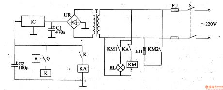
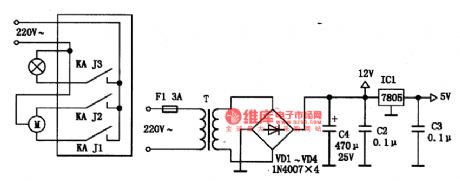
The thermostat circuit for farm is composed of the power supply circuit and constant temperature control circuit, and the circuit is shown in Figure 4-40. Power supply circuit is composed of the power switch S, fuse FU, power transformer T, bridge rectifier UR, filter capacitors Cl, C2, and three-terminal voltage regulator integrated circuit IC. Constant temperature control circuit is composed of the electric contact thermometer Q, relay K, intermediate relay KA, AC contactor KM, electric heater EH and heating indicator light HL. Cl and C2 select the aluminium electrolytic capacitors with the voltage above 35V.
(View)
View full Circuit Diagram | Comments | Reading(691)
Electric fence control circuit 3
Published:2011/7/25 2:42:00 Author:Ecco | Keyword: Electric fence control
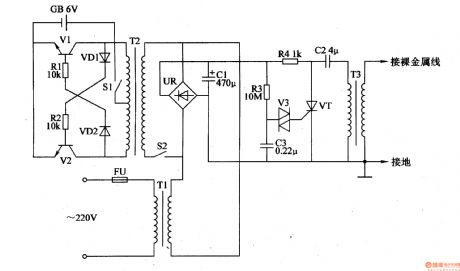
The electric fence control circuit is composed of the power supply circuit, self-excited multivibrator and high-voltage generator circuit, and it is shown in Figure 4-28. Power supply circuit is composed of the fuse FU, power transformer Tl, bridge rectifier UR, filter capacitor Cl, battery GB, power switches S1, S2. Self-excited multivibrator circuit consists of transistors Vl, V2, resistors Rl, R2, diodes VDl, VD2, and the oscillation step-up transformer T2. The high-voltage generator circuit is composed of thyristor VT, two-way trigger diode V3, resistors R3, R4, capacitors C2, C3, and step-up pulse transformer T3.
(View)
View full Circuit Diagram | Comments | Reading(6010)
Electric fence control circuit 2
Published:2011/7/25 2:38:00 Author:Ecco | Keyword: Electric fence control
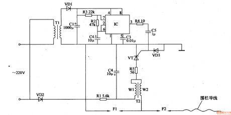
Electric fence control circuit is composed of the power supply circuit, pulse generator and high-voltage circuit, and it is shown in Figure 4-27. Power supply circuit is composed of the power transformer Tl, rectifier diodes VDl, VD2, filter capacitors Cl, C2 and resistor Rl. Pulse generator is composed of the time-base integrated circuit IC, resistor m, R3 and capacitor C3. High-voltage circuit consists of step-up transformer T2, SCR VT, resistors R4, R5, capacitor C5, diode VD3 and spark gap Fl.
(View)
View full Circuit Diagram | Comments | Reading(3890)
Water Activated Alarm
Published:2011/7/24 22:33:00 Author:Ecco | Keyword: Water Activated Alarm
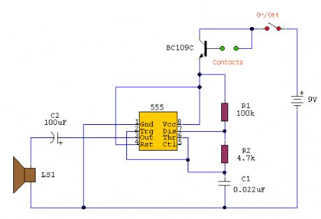
The circuit uses a 555 timer wired as an astable oscillator and powered by the emitter current of the BC109C. Under dry conditions, the transistor will have no bias current and be fully off. However as the probes get wet the transistor will conduct and sounding the alarm.An On/Off switch is provided and remember to use a non-reactive metal for the probe contacts. Gold or silver plated contacts from an old relay may be used, however a cheap alternative is to wire alternate copper strips from a piece of veroboard. These will eventually oxidize over but as very little current is flowing in the base circuit, the higher impedance caused by oxidization is not important. No base resistor is necessary as the transistor is in emitter follower, current limit being the impedance at the emitter (the oscillator circuit). (View)
View full Circuit Diagram | Comments | Reading(1)
Bag anti-lost alarm circuit
Published:2011/7/25 2:17:00 Author:Christina | Keyword: Bag, anti-lost, alarm
The bag anti-lost alarm circuit is composed of the transmitter and receiver, the transmitter is in the bag, and the receiver goes with you, when the bag leaves the owner of 5-10 meters, the receiver will send out the alarm sound to warn the owner.
The principle diagram of the transmitter is as shown in the figure.
(View)
View full Circuit Diagram | Comments | Reading(1898)
Timing controller circuit diagram
Published:2011/7/24 23:04:00 Author:Ecco | Keyword: Timing controller
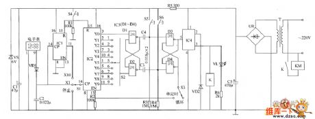
The timing controller circuit is composed of the power supply circuit, clock signal generator, counting distributor circuit, trigger circuit and control output circuit, and the circuit is shown as the chart. Power supply circuit is composed of the power transformer T, bridge rectifier UR, filter capacitors C1, C5, current limiting resistor R5 and Zener diode VS. The clock signal generator is composed of the electronic watch, diode VD1, capacitor C2 and count divider integrated circuit IC1. Counting distributor circuit consists of the counting distributor integrated circuit IC2, resistors R1, R2, timer selector switches S1, S2 and reset button.
(View)
View full Circuit Diagram | Comments | Reading(697)
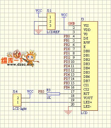
LCD module and controller circuit diagram
Published:2011/7/24 22:41:00 Author:Ecco | Keyword: LCD module , controller
View full Circuit Diagram | Comments | Reading(597)
Simple programmable adjustable timing sequence controller circuit
Published:2011/7/24 21:06:00 Author:Christina | Keyword: Simple, programmable, adjustable, timing sequence, controller circuit
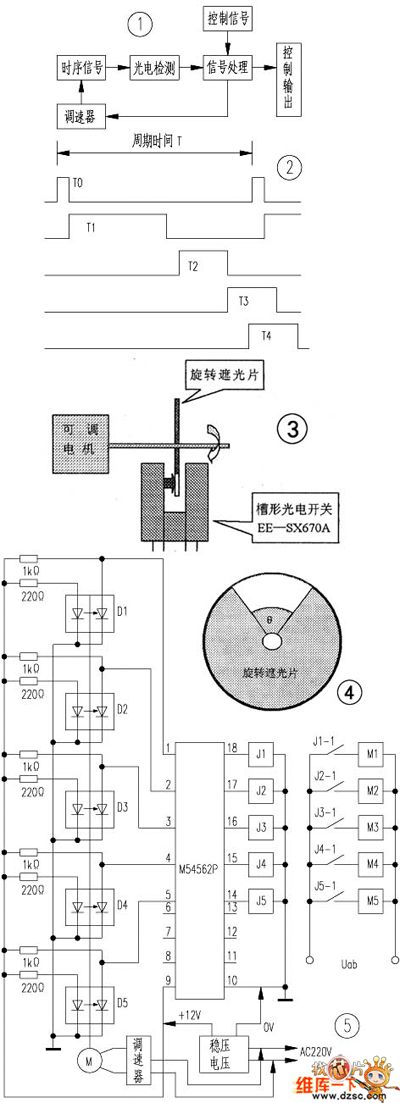
You can use the adjustable motor to drive the round metal (50mm diameter and has the gap design), and this also makes the photoelectric switches which are installed at the both sides of the sheet iron outer perimeter produce the pulse signal (groove shape, the model is: omron ee-sx670a), and this pulse is processed to be the available control signal.
So when we are manufacturing the automatic package machine, we need to use five coaxial rotating shading sheets to control the five actions of t0、t1、t2、t3、t4 respectively.
(View)
View full Circuit Diagram | Comments | Reading(642)
Simple sound control music color light controller circuit
Published:2011/7/24 21:53:00 Author:Christina | Keyword: Simple, sound control, music, color light, controller circuit
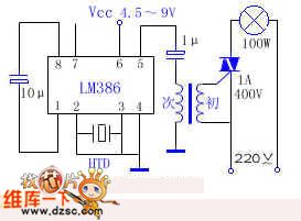
A lots of sound control music color light controller circuits have many audio signal amplifications and three or four transistors, so the circuit is hard to adjust, for some beginners, it is hard to assemble and install. So I use a audio amplification integrated circuit lm386 to assemble and install a music color light controller, the external circuits are very simple. The cost is less than five yuan, and it is very sensitive. The circuit is as shown in the figure, the transformer is the output transformer of the portable radio. The htd is the piezoelectric ceramics with the diameter of 27mm. This circuit can drive a incandescent bulb with the power of lower than 150W.
(View)
View full Circuit Diagram | Comments | Reading(1487)
Chasing type circulation color light control IC Y997A circuit
Published:2011/7/24 22:38:00 Author:Christina | Keyword: Chasing type, circulation, color light, control IC
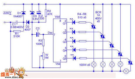
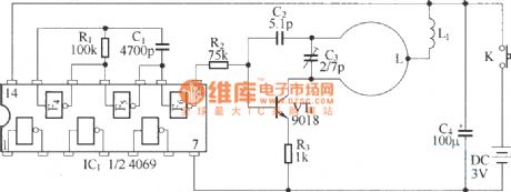
The Y997A is designed as one kind of special flash integrated circuit that uses the standard 8-pin dual-row DIP plastic package. The parameters are as shown: the static current is lower than 5mA, the power supply voltage is 1.8-7V. When the voltage of the output port is 3V, the output current is 15mA, when the voltage is 5V, the output current is 50mA. The breakdown voltage of the output port MOSFET is higher than 18V.
The pin functions of the Y997A are as shown: the VDD power supply of pin-8 is positive. The Vss power supply of pin-1 is negative. The pin-7 dsc is the oscillation input port, you can change the flash frequency by changing the values of the external resistance containers. The pin-2 to pin-6 are q1-q5, they are the flash output port; Y997A is the chasing type circulation color light control IC, the flash sequence is q1→q2→q3→q4→q5→q1→q2....
(View)
View full Circuit Diagram | Comments | Reading(683)
Minimum cost sound control music color light circuit
Published:2011/7/25 1:43:00 Author:Christina | Keyword: Minimum cost, sound control, music, color light
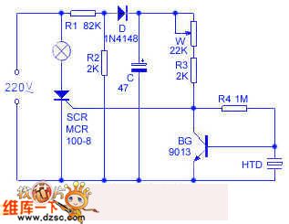
The color light controller circuit is as shown in the figure, the resistance step-down half-wave full-wave circuit is composed of the r1, r2, d and c, it outputs the 3V DC current to the control circuit of SCR. The piezoelectric ceramics htd is used as the sound-electric transducer, you can make the bg collector output the low level by adjusting w, the scr cuts off, the color light turns off. When the htd receives the acoustic signal, the electrical level of the bg collector will rise up, the scr turns on, the color light can flash with the music rhythm of the indoor radio. w can be used to adjust the sound control sensitivity, when the w is from high to low, the sound sensitivity is from low to high, when the w is too low, the light will turn on, so the circuit loss the sound control function.
(View)
View full Circuit Diagram | Comments | Reading(1169)
CMS-O01--the single chip microcomputer control integrated circuit
Published:2011/7/15 19:15:00 Author:Borg | Keyword: single chip microcomputer, integrated circuit
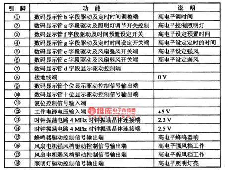
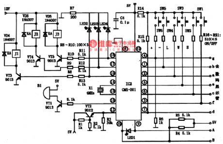
CMS-O01 is a single chip microcomputer control integrated circuit, which is widely used in the electric control systems as the main chip of all kinds of kitchen ventilators, such as Tuoli.1.function featuresCMS-O01 integrated circuit contains the CPU clock oscillating circuit, dual-bit 7-stage LED digit tube drive control circuit, reset circuit, drive control circuits all types of relays and buzzers and other affiliated function circuits.2.pin functions and dataCMS-O01 is in the 18-pin dual in-line package.
(View)
View full Circuit Diagram | Comments | Reading(679)
Household simple flashing wall lamp controller circuit
Published:2011/7/25 2:11:00 Author:Christina | Keyword: Household, simple, flashing, wall lamp, controller
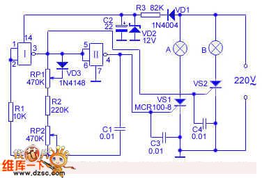
The circuit principle: the circuit is as shown in the figure, the simple resistance step-down half-wave full-wave circuit is composed of vd1, vd2, r3 and c2, it outputs the 12V DC to the IC. The multivibrator is composed of the NOT gate I and II, you can change the oscillation frequency by adjusting the rp1 and rp2. The VD3 has the isolation effect to prevent the influence between rp1 and rp2 when you are adjusting rp1. When the circuit is start-up, the NAND gate output port alternately outputs the high level and the low level. When pin-3 outputs the high level, the thyristor vs2 conducts, the light b turns on, at this time the pin-4 has the low level, the light a will not turns on; when pin-3 outputs the low level, the thyristor vs2 cuts off, the light b turns off.
(View)
View full Circuit Diagram | Comments | Reading(791)
Y-connection three-phase motor low speed running and braking in reverse circuit
Published:2011/7/14 20:29:00 Author:Lucas | Keyword: KMF, three-phase motor
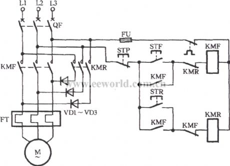
Just as shown in the circuit, high-power semiconductor diode is used for lowering pressure to achieve the low-speed operation of the electric motor. When STF is pressed, AC contactor KMF pulls with the gain of electricity and the motor M runs forward. When STP is pressed, the motor M would power off. If STR is pressed at this time, diode VD1 ~ VD3 are inducted by the reverse contactors KMR. And the power is rectified. The DC current is input to three-phase stator winding. When the M does not turn, press STP for braking the M. If the motor is expected to run in alt= Y-connection three-phase motor low speed running and braking in reverse.
(View)
View full Circuit Diagram | Comments | Reading(4860)
μPC1100 control circuit, main features and pin of DC-DC circuit and power supply monitor
Published:2011/7/20 19:04:00 Author:Lucas | Keyword: control circuit, main features , pin , DC-DC circuit , power supply monitor
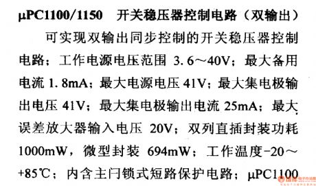
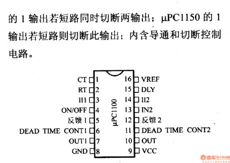
μPC1100/1150 switching regulatorcontrol circuit(dual output)
It can achieve dual output synchronous controlled switching regulator control circuit; supply voltage range is 3.6 ~ 40V; the maximum standby current is 1.8mA; the maximum supply voltage is 41V; the maximum collector output voltage is 41V; the maximum collector output current is 25mA; maximum error amplifier input voltage is 20V; dual in-line package power is 1000mW, and micro-encapsulation is 694mW; Operating Temperature is -20 ~ +85 ℃;it contains the main door short-circuit protection circuit; if μPC1100 1 output is short-circuit, the dual output should be cut off.
(View)
View full Circuit Diagram | Comments | Reading(782)
| Pages:193/312 At 20181182183184185186187188189190191192193194195196197198199200Under 20 |
Circuit Categories
power supply circuit
Amplifier Circuit
Basic Circuit
LED and Light Circuit
Sensor Circuit
Signal Processing
Electrical Equipment Circuit
Control Circuit
Remote Control Circuit
A/D-D/A Converter Circuit
Audio Circuit
Measuring and Test Circuit
Communication Circuit
Computer-Related Circuit
555 Circuit
Automotive Circuit
Repairing Circuit