
Control Circuit
Index 183
EAR_PROTECTOR
Published:2009/6/17 21:02:00 Author:May
The ear protector is actually a peak audio- detector/shutdown circuit that disables the amplifier through its chip-disable input when the output volume of an amplifier reaches the set level. The cir-cuit, although intended for the MC34119 amplifier, should work with similar IC devices or applications. (View)
View full Circuit Diagram | Comments | Reading(867)
MODEM_FAX_PROTECTOR_FOR_TWO_COMPUTERS
Published:2009/6/17 21:01:00 Author:May
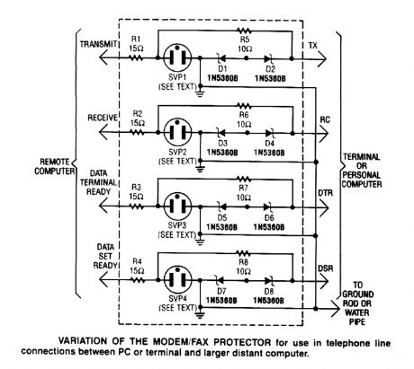
This modem/fax protector can be used in telephone-line connections betweenaPC or a terminal and a distant computer. In this circuit, the SVPs (surge voltage protectors) are at 230V.A good ground is a must for effective operation. (View)
View full Circuit Diagram | Comments | Reading(1223)
TIMED_SAFETY_CIRCUIT
Published:2009/6/17 20:57:00 Author:May
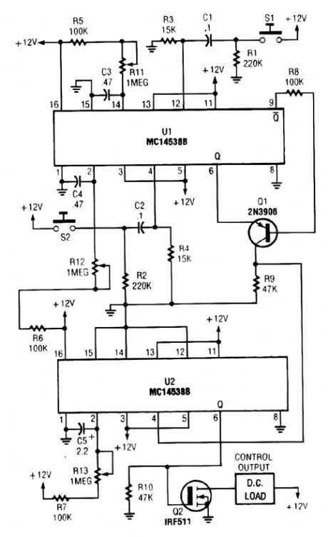
When S1 is closed, pin 9 of U1 goes low, turning on Q1 for a preset period. If S2 is closed during this period, Q2 is turned on for a preset period. R11 and R13 set the two time periods. (View)
View full Circuit Diagram | Comments | Reading(619)
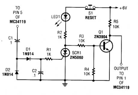
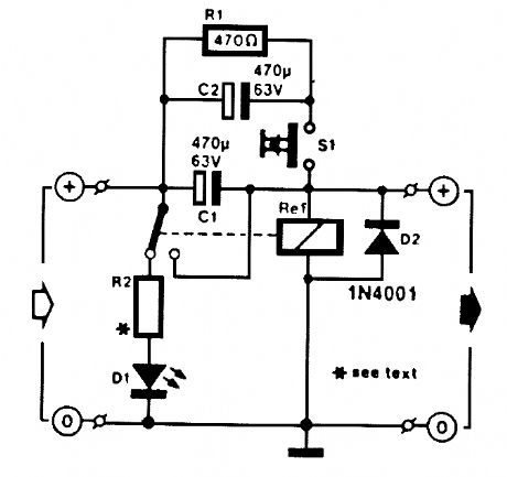
OVERVOLTAGE_PROTECTION_CIRCUIT
Published:2009/6/17 20:55:00 Author:May
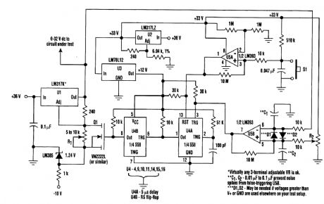
When testing a circuit, a source of voltage that is variable and has overvoltage shutdown is very useful. In this circuit, R1 is adjusted to 1 to 2 V below the eventual shutdown threshold. R2 sets the trip voltage. When this voltage is reached, the circuit shuts the voltage to the circuit under test down. To reset, reduce R1 below trip threshold and depress reset switch S1. (View)
View full Circuit Diagram | Comments | Reading(404)
MODEM_PROTECTOR
Published:2009/6/17 20:51:00 Author:May
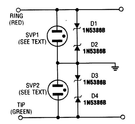
This protector uses surge voltage protectors rated at 230-V breakdown. An effective ground should be used. (View)
View full Circuit Diagram | Comments | Reading(1051)
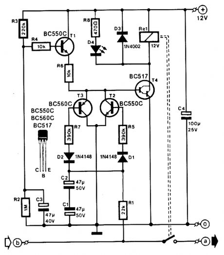
RELAY_FUSE_FOR_POWER_SUPPLIES
Published:2009/6/17 20:45:00 Author:May
A method of adding overload protection to a power supply using a relay is shown. In each cir-cuit, the relay must be reset by a momentary switch using a charge on capacitor C2. This prevents overload ifthe short still exists. (View)
View full Circuit Diagram | Comments | Reading(1241)
SPEAKER_PROTECTOR
Published:2009/6/17 20:36:00 Author:May
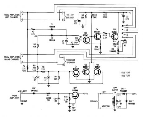
Most of the transistors in this speaker protector function as switches. Normally, Q4, Q5, and K1 are on and the speakers are connected to the amplifier. However, if a large dc voltage appears at an amplifier output, either Q3, or Q1 and Q2 turn on; biasing Q4 off. That action turns Q5 off, de-ener-gizes the relay, and disconnects the speakers from the amplifier. Components D1, D2, and Q6 form the overdrive-protection circuit. (View)
View full Circuit Diagram | Comments | Reading(4300)
WATCH_TICK_TIMER
Published:2009/6/17 3:56:00 Author:May

This circuit adapts a frequency counter to measure intervals. It was originally used as a shutter speed checker for a photo ap-plication. The watch ticks are clipped and shaped and formed into a square wave. This square wave is used to gate an accurately known clock (1-MHz TTL XTAL OSC) and an external counter is used to directly count the clock pulses during the interval to be measured. A 1-MHz clock can be used to measure to a resolution of 1 psec. Accuracy = ± time base ±1 μs ±t1 count LSB. (View)
View full Circuit Diagram | Comments | Reading(824)
DUAL_CONTROL_SWITCH_USES_ac_SIGNALS
Published:2009/6/17 3:37:00 Author:May
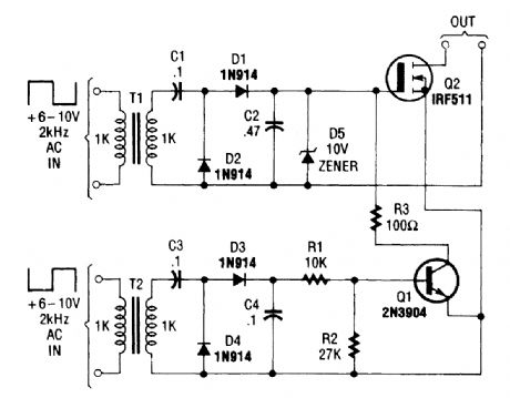
The Dual-Control Switch uses two 6-10-Vac sources to trigger the circuit on and off; one source for each function. (View)
View full Circuit Diagram | Comments | Reading(779)
SIMPLE_ac_VOLTAGE_CONTROL
Published:2009/6/17 3:34:00 Author:May
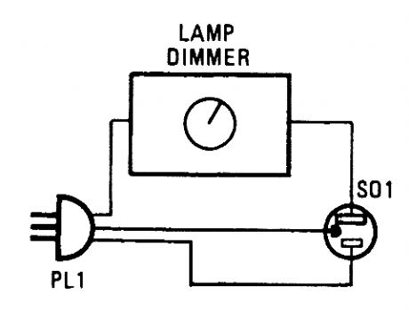
Lamp dimmers can be used for more than just controlling lights. Just provide one with an ac line cord and a socket, and discover just how useful they can be. (View)
View full Circuit Diagram | Comments | Reading(691)
VCR_TV_ON_OFF_CONTROL
Published:2009/6/17 3:28:00 Author:May
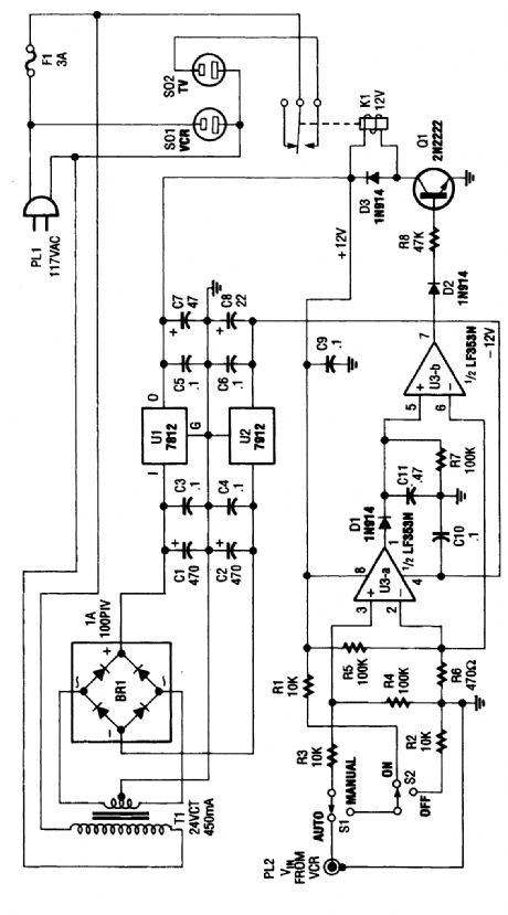
This circuit senses the video from the VCR. When the VCR is turned on, video signal is amplified by U3A and B to drive Q1, actibating K1. In this manner, it is not necessary to turn on and off two video decices every time. In many cases, this avoids the use of a cable box, the cable-ready VCR performing this function. (View)
View full Circuit Diagram | Comments | Reading(791)
LOAD_SENSING_SOLID_STATE_SWITCH
Published:2009/6/17 3:17:00 Author:May
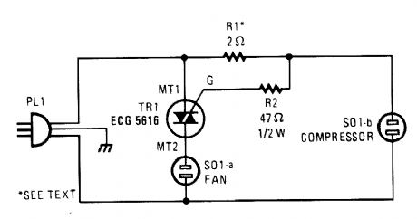
When this triac circuit senses current flow through SOl-a, it activates the device plugged into SOl-b. The values of the resistors must be chosen for the specific devices to be plugged in. (View)
View full Circuit Diagram | Comments | Reading(948)
PC_PASSWORD_PROTECTION
Published:2009/6/17 3:12:00 Author:May
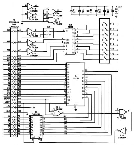
With this circuit, a PC will be protected, requiring a password to boot. After three times, the computer will have to have a cold reboot and the password tried again. Software for this system is available-consult the reference for further details. (View)
View full Circuit Diagram | Comments | Reading(1119)
DARK_ACTIVATED_RELAY
Published:2009/6/17 2:43:00 Author:May
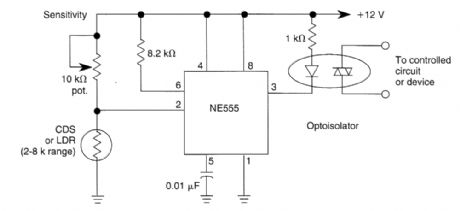
Configuring a 555 IC as shown yields a dark-activated relay with low hysteresis. CDS or LDR should be in the 2k to 8k range at desired light level. (View)
View full Circuit Diagram | Comments | Reading(1901)
SIMPLE_NONLATCHING_PHOTOCELL_SWITCH
Published:2009/6/17 2:41:00 Author:May
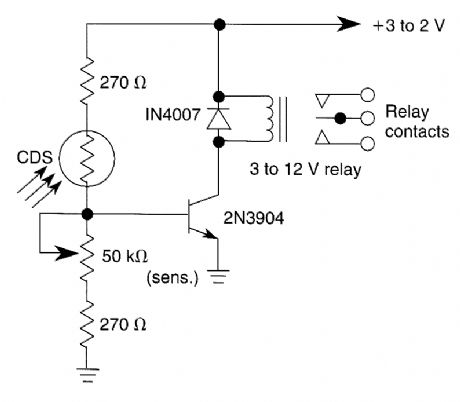
A CDS photocell is used to drive the relay.The circuit operates from a +12 V supply. (View)
View full Circuit Diagram | Comments | Reading(2300)
SELF_LATCHING_LIGHT_ACTIVATED_SWITCH
Published:2009/6/17 2:40:00 Author:May
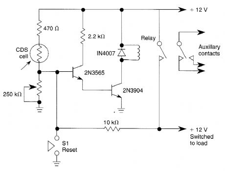
When light strikes the CDS cell it turns on the transistors which activates the relay which latches. Depressing 51 grounds the base of the 2N3565 and the relay resets. The 250 k potentiometer adjusts the sensitivity of the circuit. (View)
View full Circuit Diagram | Comments | Reading(1237)
ELECTRONIC_CW“BUG”KEYER
Published:2009/6/17 2:40:00 Author:May
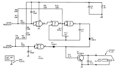
This keyer uses skin conductivity to simulate the old-fashioned mechanical CW bug keyer. When the “dit”paddle is touched the bias on the inverter, IC1-a is shunted to ground, and it produces a logic high, causing oscillator sections C&D to generate a low-frequency square wave keying Ql for a series of “dits.” When the “dah”paddle is touched, section b produces a logic high, driving keyer Q1 on. (View)
View full Circuit Diagram | Comments | Reading(2496)
PRECISION_LIGHT_SENSITIVE_RELAY_SWITCH
Published:2009/6/17 2:40:00 Author:May
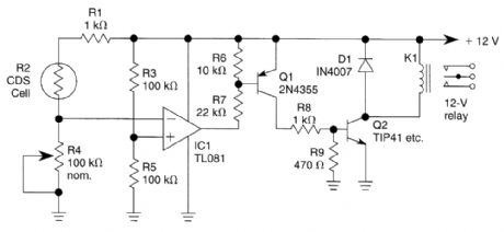
A CDS cell in a bridge circuit with an op amp provides a simple means of operating a relay at a predetermined light level. Potentiometer R4 sets the sensitivity. (View)
View full Circuit Diagram | Comments | Reading(1149)
BINARY_CLOCK
Published:2009/6/17 2:35:00 Author:May
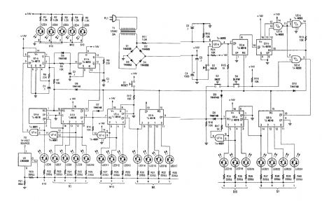
This circuit is an unusual clock in that the LEDs are bi-color red/green displays that indicate the Lime in binary coded decimal form.LEDs 21 through 24 read out secondsLEDs 5, 18, 19, and 20 read out 105 secondsLEDs 14 through 17 read out in minutesLEDs 4, 11, 12, and 13 read out in 105 minutes LEDs 7 through 10 read out the hoursLEDs 1, 2, 3, and 6 read out tens of hoursThe 60-Hz line is used as a timebase. (View)
View full Circuit Diagram | Comments | Reading(2809)
DARK_ACTIVATED_SWITCH
Published:2009/6/17 2:34:00 Author:May
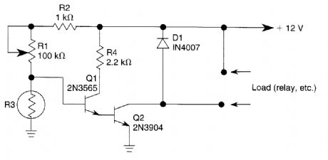
In this circuit, lowering of the light level on the CDS cell turns on Q1 and Q2 which switches on the load which could be a relay, light, etc. (View)
View full Circuit Diagram | Comments | Reading(133)
| Pages:183/312 At 20181182183184185186187188189190191192193194195196197198199200Under 20 |
Circuit Categories
power supply circuit
Amplifier Circuit
Basic Circuit
LED and Light Circuit
Sensor Circuit
Signal Processing
Electrical Equipment Circuit
Control Circuit
Remote Control Circuit
A/D-D/A Converter Circuit
Audio Circuit
Measuring and Test Circuit
Communication Circuit
Computer-Related Circuit
555 Circuit
Automotive Circuit
Repairing Circuit