
Control Circuit
Index 189
The industrial oil furnace controller (2)
Published:2011/7/23 2:42:00 Author:qqtang | Keyword: oil furnace controller
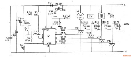
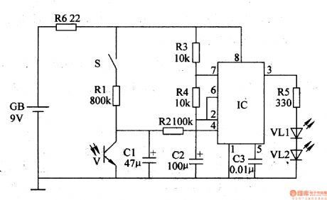
The working principle of the circuit The industrial oil furnace controller consists of the power supply circuit, detection/ignition control circuit and control executing circuit, see as figure 8-89.
The power supply circuit consists of the capacitor C6, releasing resistor R5, regulated diode VS1, rectifier diode VD and filter capacitors of C1 and C2. The detection/ignition control circuit consists of the resistor R1-R4, light sensitive resistor RG, capacitor C3-C5, reset key S, regulated diode VS2 and control integrated circuit IC. (View)
View full Circuit Diagram | Comments | Reading(819)
The car sound burglarproof alarm (2)
Published:2011/7/23 2:56:00 Author:qqtang | Keyword: burglarproof alarm
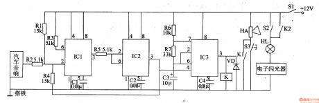
The working principle of the circuitThe car sound burglarproof alarm consists of the trigger control circuit and alarm circuit, see as figure 7-102.
The trigger control circuit consists of the time-based integrated circuits of IC1 and IC2, resistors R1-R5 and capacitors of C1 and C2.The alarm circuit consists of the time based integrated circuit IC3, resistors of R6 and R7, capacitor VD, relay K and the flash HL on the car, loudspeaker HA and so on. (View)
View full Circuit Diagram | Comments | Reading(610)
The automobile burglarproof alarm (2)
Published:2011/7/23 3:24:00 Author:qqtang | Keyword: burglarproof alarm
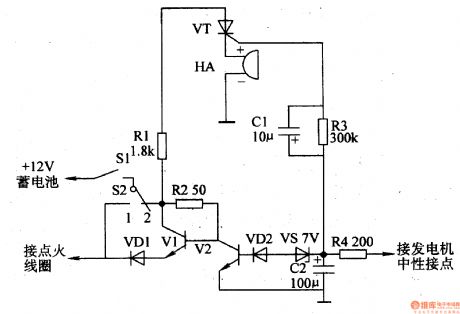
The working principle of the circuit The burglarproof alarm circuit consists of the burglarproof control circuit and trigger alarm circuit, see as figure 7-80.
The burglarproof control circuit consists of the car igniting switch S1, burglar switch S2, diodes of VD1 and VD2, transistor V1 and V2, resistor R2 and capacitor C2. The trigger alarm circuit consists of the resistors (R1, R3 and R4), capacitor C1, thyristor VT and buzzer HA. (View)
View full Circuit Diagram | Comments | Reading(520)
Long Time Delay Sound Control Light Switch Circuit Composed of CD4011
Published:2011/7/23 7:09:00 Author:Sue | Keyword: Long Time Delay, Sound Control, Light Switch
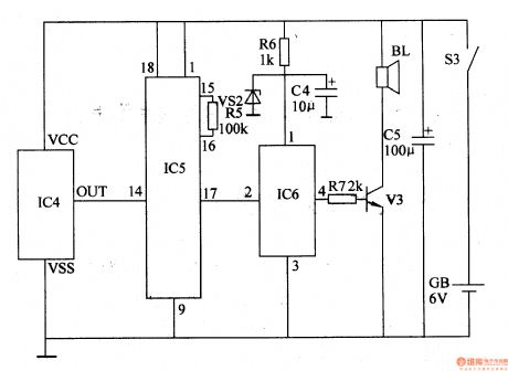
The long time delay sound control light switch shown in the picture has the longest delay time of 1h. It is suitable for primary and secondary school students tohave time control when they are doing the homework. Then students will have arest after they have studied for an hour. This can improve their learning efficiency. The picture shows the circuit, which consists of acoustic sensor, monostable delay circuit, relay, drive circuit and power circuit.
(View)
View full Circuit Diagram | Comments | Reading(825)
Bathroom Gating Light Exhaust Switch Circuit Composed of CD4001
Published:2011/7/27 5:39:00 Author:Sue | Keyword: Bathroom, Gating, Light Exhaust Switch
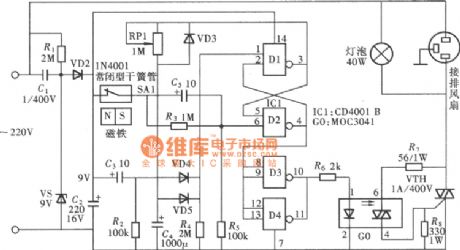
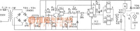
The control circuit uses gating technology. When someone comes in the room, the gating switch will start the light and exhaust fan automatically which will stop working automatically when it reaches the delay time. It is very convenient and the picture shows the circuit. The circuit uses one 412 input terminal or NOT GATE CD4001, two gates D1,D2 of which will compose one no triggered monostable delay circuit. Its delay time is decided by RP1's resistance value and C4's capacitance. The other two gates D3,D4 are connected and will be used as phase inverter and amplifier. (View)
View full Circuit Diagram | Comments | Reading(2527)
The automobile burglarproof alarm (1)
Published:2011/7/23 3:19:00 Author:qqtang | Keyword: burglarproof alarm
The working principle of the circuit The trigger alarm emitter circuit consists of the electric switch circuit, regulated filter circuit and encoding wireless emitter circuit, see as figure 7-78.
The electric switch circuit consists of the burglar switch S2, thyristor VT, transistors of V1 and V2, diodes of VD1 and VD2, resistors R1-R3, capacitors of C1 and C2, regulated diode VS1 and so on. The regulated filter circuit consists of the 3-terminal regulator IC1 and filter capacitor C3 (View)
View full Circuit Diagram | Comments | Reading(668)
Touch Bathroom Exhaust Fan Time Delay Switch Circuit Composed of CD4069
Published:2011/7/27 5:40:00 Author:Sue | Keyword: Touch, Bathroom Exhaust Fan, Time Delay Switch
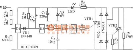
In the picture, the touch exhaust fan time delay switch consists of only one CD4069 and thyristor. It has simple structure and low production cost, and is affordable. The circuit is shown in the picture. The circuit structure is very simple. It connects CD4069's four phase inverters in series and time delay circuit R,C are added into it. The input terminal is connected to touch film M through high-value resistor R1,R2, and D4's output terminal is connected to the thyristor's trigger terminal. (View)
View full Circuit Diagram | Comments | Reading(2127)
Touch Lamp Switch Circuit Composed of CD4009
Published:2011/7/21 20:05:00 Author:Sue | Keyword: Touch, Lamp Switch
The touch lamp switch can turn on or turn off the lamp by being touched by any body part of people. For some certain occasions, this function is very meaningful. The picture shows how it is composed. The circuit uses only one hex inverter CD4069. Two gates D1,D2 of it compose a negative pulse bistable flip-flop. It uses the other gate D3 to compose an phase inverter. Then it uses a relay driving tube to drive a relay to achieve the lamp switch control. (View)
View full Circuit Diagram | Comments | Reading(1607)
Summing Integrator Circuit
Published:2011/7/21 1:08:00 Author:Sue | Keyword: Summing, Integrator
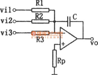
The picture shows the summing integrator circuit. It is named as summing integratorfor thereason thatthe circuit has many input return circuits.
Figure1 Summing Integrator Circuit (View)
View full Circuit Diagram | Comments | Reading(1511)
Differential Integrator Circuit
Published:2011/7/21 1:05:00 Author:Sue | Keyword: Differential, Integrator
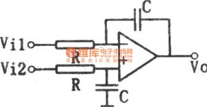
The picture shows the differential integrator circuit. Put R,C on the same phase side of the basic integrator according to the balanced symmetrical structure, then we will get such differential integrator circuit.
Figure1 Differential Integrator Circuit (View)
View full Circuit Diagram | Comments | Reading(2890)
Low Drift Differentiator Circuit
Published:2011/7/22 7:29:00 Author:Sue | Keyword: Low Drift, Differentiator
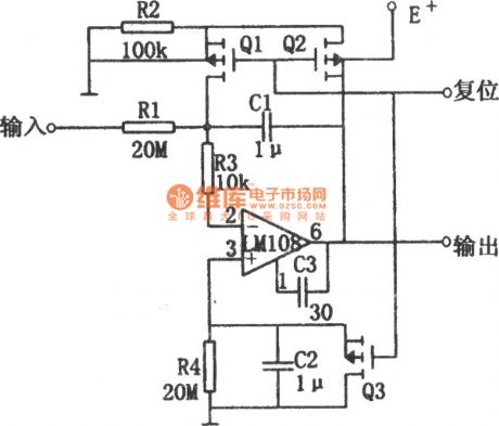
The differentiator shown in the circuit has small drift which will not exceed 500μV/s within the temperature rangefrom -55C to +125C. In the picture, the basic differentiator consists of operational amplifier, resistor R1 and capacitor C1. In order to improve the stability of the differentiator, the circuit adds resistor R4 and capacitor C2(R4=R1,C2=C1) to the operational amplifier's non inverting input terminal which will differentiate the input bias current. When the circuit is reset, field effec tube Q1 and Q2 will make the capacitor C1 short, which will prevent the input bias current from causing offset voltage. When Q1 and Q2are disconnected, the circuit begins to integrate. Then the bias current which flows through R1 will generate offset voltage. (View)
View full Circuit Diagram | Comments | Reading(685)
The engine oil volume detector
Published:2011/7/23 8:46:00 Author:qqtang | Keyword: oil volume detector
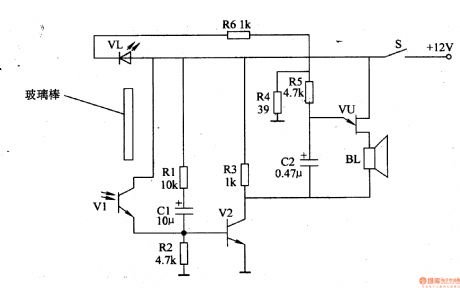
The working principle of the circuitThe engine oil volume detector consists of the photoelectric control circuit and sound alarm circuit, see as figure 7-63.
The photoelectric control circuit consists of the LED VL, light sensitive transistor V1, resistors of R1-R3 and R6, capacitor C1 and transistor V2.The sound alarm circuit consists of the resistor(R4, R5), capacitor C2, single knot transistor VU and loudspeaker BL. (View)
View full Circuit Diagram | Comments | Reading(749)
The seeder channel block alarm (2)
Published:2011/7/23 22:05:00 Author:qqtang | Keyword: seeder channel, block alarm
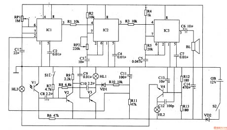
The working principle of the circuitThe seeder channel block alarm circuit consists of the photoelectric control circuit, single steady circuit, 1HZ multi-resonance oscillator, 1KHZ multi-resonance oscillator phase indicator circuit, see as figure 4-104.
The photoelectric control circuit consists of the indicators HL1 and HL3, transistors V2 and V3, resistors R6-R11, capacitors C8-C11, diode VD1 and reset key S1.The astable circuit consists of the potentiometer RP1, capacitors C1 and C2, time-base integrated circuit IC1. (View)
View full Circuit Diagram | Comments | Reading(635)
The bicycle night flashing tail lamp
Published:2011/7/23 21:57:00 Author:qqtang | Keyword: tail lamp, bicycle
The working principle of the circuit The bicycle night flashing tail lamp circuit consists of light control circuit, trigger control circuit, astable multi-resonance oscillator and LED flashing circuit, see as figure 7-37.
The light control circuit consists of the light sensitive transistor V, capacitor C1, resistor R2 and 4-pin internal circuit of the time-based integrated circuit IC.The trigger control circuit consists of the trigger switch S, resistors R1 and R2 and capacitor C1. (View)
View full Circuit Diagram | Comments | Reading(1733)
The fuse box indicator (1)
Published:2011/7/23 21:45:00 Author:qqtang | Keyword: fuse box, indicator
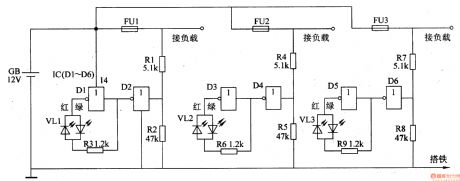
Here is to introduce a fuse box indicator composed of the CMOS digital integrated circuit and double color LED VL, which can monitor the fuse box working state in the car. When the fuse box is normal, VL is glowing green light; when the fuse box is broken down, VL is glowing red light.The working principle of the circuitThe fuse box indicator circuit consists of resistors R1-R9, NOR gate integrated circuit IC(Dl-D6) and double color LED VL1-VL3, see as figure 7-44.
(View)
View full Circuit Diagram | Comments | Reading(937)
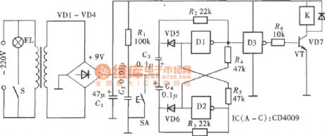
Light control road lamp automatic control circuit
Published:2011/7/14 23:14:00 Author:Fiona | Keyword: Light control road lamp, automatic control
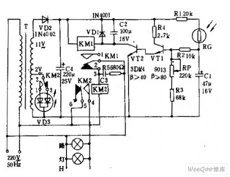
Connected to 220v AC power,the both ends of capacitor C4 will obtain ten 12v DC.At night,photoresistance RG is a high resistance,transistor VTl, v1,v2 are closed.The relay KMl has no power,the contacts 2-3 of KMl are closed.AC relay KM2 works with power.The contacts l-2 ,4-5 of KM2 are closed, light-emitting diode vD3 displays $signal instructions,floodlight H automatically kindle.At dawn,RG is a low resistance,VT1 conducts when it obtains base current,the radiation high potential output makes vT2 saturated conductivity. (View)
View full Circuit Diagram | Comments | Reading(956)
The division circuit for ratio calculation
Published:2011/7/14 23:04:00 Author:Fiona | Keyword: ratio calculation
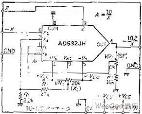
Circuit function
This circuit is the division circuit that the input signal Z is divided by X. Besides operating EO = 10Z / (-X) and calculating the ratio or percentage,it also can be used as AGC amplifier (A=1/X) which inputs control voltage from the X side. But it can't do large-scale operations. If the input X as the denominator turns smaller, 1 / X will increase,.When X = 0, the gain is infinite, so for division, the range is limited.
Circuit work
If the IC is used as a multiplication, the output voltage feedbacks to the Y input, does the 1 / X calculation, and then multiplies by Z. Because of adding a multiplication unit in the OP amplifier feedback loop, the X input turns smaller so that the circuit would become unstable. and the X values are different, closed-loop frequency characteristics will change because of X's different values. Pay attention to use it.
Z-ended input signal has been inverted in the output, the X input only can use the negative voltage . When X = 10V,the circuit uses VR2 to adjust scaling factor to make A = 1. It also can use VR2 to do disorders adjustment of dynamic range of the division circuit.After reducing the variable range, in order to facilitate adjustment, it addsvoltage divider circuit composed of the R1, R2. Input 1V from Z,input 1V from X, adjust VR1 to make the output to be -10V (A =- 10).when Z = 0.1V, X =- 0.1V,it also can get 10V output, but it can not guarantee the accuracy and stability Degrees. In addition, the frequency response changes with the value which is inputed from X.This point also should be noted. (View)
View full Circuit Diagram | Comments | Reading(661)
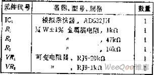
Five flash lamp string circuit (3)(Y977A)
Published:2011/7/5 21:59:00 Author:zj | Keyword: Five flash, lamp string circuit
As thecircuit shown in the figure , VTH1 ~ VTH5can useMAC94A4 type small plastic bidirectional thyristor. The maximum drive currentis 1A. (View)
View full Circuit Diagram | Comments | Reading(696)
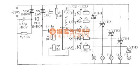
Light control delay lamp circuit (2)
Published:2011/7/4 22:40:00 Author:zj | Keyword: Light control, delay lamp
As the diagram shows, it can be used as bedside wall lamp circuit. When you turn off the light to go to bed at night, it can lights up for about 1 minute. It can bring coziness to the bedroom andconvenience to life. This circuit is mainly used for auxiliary lightingafter lights out. Light E should use 5~15W low power lamp. (View)
View full Circuit Diagram | Comments | Reading(892)
Arbitrary pulse selection circuit diagram 2(CD40178、CD40106B)
Published:2011/7/14 22:51:00 Author:zj | Keyword: Arbitrary pulse, selection circuit diagram
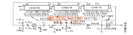
As shown in the diagram, the circuit structure is simple.The arbitrary pulse selection circuit can alsopreset the number of selected pulsesdirectly using decimalmethod.It is very convenient.
(View)
View full Circuit Diagram | Comments | Reading(1016)
| Pages:189/312 At 20181182183184185186187188189190191192193194195196197198199200Under 20 |
Circuit Categories
power supply circuit
Amplifier Circuit
Basic Circuit
LED and Light Circuit
Sensor Circuit
Signal Processing
Electrical Equipment Circuit
Control Circuit
Remote Control Circuit
A/D-D/A Converter Circuit
Audio Circuit
Measuring and Test Circuit
Communication Circuit
Computer-Related Circuit
555 Circuit
Automotive Circuit
Repairing Circuit