
Index 262
Beijing Wuzhou elevator control circuit (1)
Published:2011/5/19 8:36:00 Author:TaoXi | Keyword: Beijing Wuzhou, elevator, control circuit
Beijing Wuzhou elevator control circuit (1) (View)
View full Circuit Diagram | Comments | Reading(513)
Beijing Wuzhou elevator safety loop and band-type brake circuit
Published:2011/5/19 8:39:00 Author:TaoXi | Keyword: Beijing Wuzhou, elevator, safety loop, band-type brake
Beijing Wuzhou elevator safety loop and band-type brake circuit (View)
View full Circuit Diagram | Comments | Reading(407)
Toshiba CV60 elevator band-type braking circuit
Published:2011/5/19 8:52:00 Author:TaoXi | Keyword: Toshiba, elevator, band-type braking circuit
Toshiba CV60 elevator band-type braking circuit (View)
View full Circuit Diagram | Comments | Reading(495)
ultra warm monitor wireless alarm system
Published:2011/5/19 10:04:00 Author:Lena | Keyword: ultra warm, wireless alarm system

(View)
View full Circuit Diagram | Comments | Reading(494)
sickroom wireless call system circuit
Published:2011/5/19 9:54:00 Author:Lena | Keyword: sickroom, wireless call system

sickroom wireless call system circuit:(a)emitter circuit;(b)receiving display circuit
(View)
View full Circuit Diagram | Comments | Reading(453)
JT-3WB type microwave burglar alarm circuit
Published:2011/5/19 9:45:00 Author:Lena | Keyword: microwave, burglar alarm

(View)
View full Circuit Diagram | Comments | Reading(434)
M18 machine core protection circuit
Published:2011/5/19 20:51:00 Author:Christina | Keyword: machine core, protection circuit
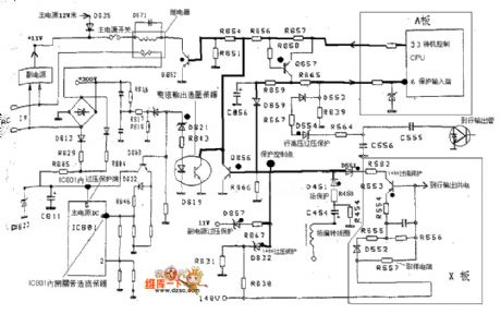
M18 machine core protection circuit:
(View)
View full Circuit Diagram | Comments | Reading(635)
The new generation touch stepless light and speed adjustment circuit NB7232
Published:2011/5/18 3:47:00 Author:TaoXi | Keyword: new generation, touch, stepless, light and speed adjustment
Related components PDF download:
NB7232
The basic working principle of the circuit (dimming example): the human body electricity and the city electricity have the same frequency, when the human body touches the touch tablet, the body electricity becomes the standard MOS electrical level with the wave cutting, the amplification and the reshaping of the input buffer stage. When the touch duration is more than 32ms and less than 332ms, the logic control part circuit is in the switching working state. When the touch duration is more than 332ms, the logic control part circuit is in the dimmer working state, the output trigger pulse phase angle continuous cyclical changes between the 41 degrees to 159 degrees, and according to the human eye sensibility, there are three processes: the fast process, the slow process and the intermittent process.
(View)
View full Circuit Diagram | Comments | Reading(805)
Household appliances electricity utilization timer circuit
Published:2011/5/19 0:43:00 Author:TaoXi | Keyword: Household appliances, electricity utilization, timer
The Household appliances electricity utilization timer circuit (View)
View full Circuit Diagram | Comments | Reading(561)
Mini contactless temperature box circuit
Published:2011/5/13 0:53:00 Author:TaoXi | Keyword: Mini, contactless, temperature box
Mini contactless temperature box circuit (View)
View full Circuit Diagram | Comments | Reading(502)
Toshiba CV-180 elevator frequency modulation door opening circuit (2)
Published:2011/5/19 9:06:00 Author:TaoXi | Keyword: Toshiba, elevator, frequency modulation, door opening circuit
Toshiba CV-180 elevator frequency modulation door opening circuit (2) (View)
View full Circuit Diagram | Comments | Reading(501)
Typical low-pass filter circuit
Published:2011/5/19 19:43:00 Author:Christina | Keyword: Typical, low-pass filter
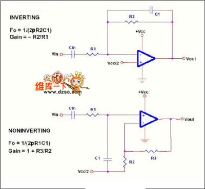
The Typical low-pass filter circuit:
(View)
View full Circuit Diagram | Comments | Reading(651)
Toshiba CV180 elevator band-type braking circuit
Published:2011/5/19 9:11:00 Author:TaoXi | Keyword: Toshiba, elevator, band-type braking circuit
Toshiba CV180 elevator band-type braking circuit (View)
View full Circuit Diagram | Comments | Reading(462)
Toshiba CV-180 elevator frequency modulation door opening circuit (1)
Published:2011/5/19 9:07:00 Author:TaoXi | Keyword: Toshiba, elevator, frequency modulation, door opening circuit
Toshiba CV-180 elevator frequency modulation door opening circuit (1) (View)
View full Circuit Diagram | Comments | Reading(398)
Flash lamp SCR trigger circuit
Published:2011/5/19 19:17:00 Author:Christina | Keyword: Flash lamp, SCR, trigger
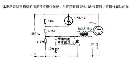
This circuit can provide protection for camera synchronous contacts, if we use the GE4JL8B instead of the SRC, this circuit can be used as the auxiliary flash.
(View)
View full Circuit Diagram | Comments | Reading(1318)
Toshiba CV180 elevator control power supply circuit
Published:2011/5/19 9:00:00 Author:TaoXi | Keyword: Toshiba, elevator, control power supply
Toshiba CV180 elevator control power supply circuit (View)
View full Circuit Diagram | Comments | Reading(460)
Police car sound and light analog circuit
Published:2011/5/19 19:02:00 Author:Christina | Keyword: Police car, sound, light, analog circuit
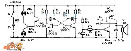
This circuit can sends out the sound of police car, meanwhile the signal parade is flashing, you can install it in the police car and fire truck models to increase the enjoyment of the toys.
In this circuit, the multivibrator oscillation circuit is composed of BG1 and BG2, the direct coupling amplifier is composed of the BG5 and BG6 to provide enough signal voltage for signal lamps.
(View)
View full Circuit Diagram | Comments | Reading(1394)
Op amp differential mode voltage breakdown input stage protection measure circuit 1
Published:2011/5/17 2:07:00 Author:Rebekka | Keyword: Op amp, differential mode v, oltage breakdown , input stage, protection measure
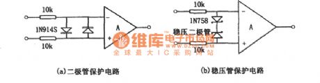
The over-voltage protection circuit that does not add an internal protection measures is shown as figure (a), (b). Figure (a) is the diode protection circuit. Figure (b) is regulator protection circuit. In the specific application, you only need to select one of them. The resistance shown in the figure is limiting current clamp resistance. Its value is up to 10kΩ and the offset voltage will not decrease. In practical applications. The input end of resistance may be the signal input. Usually, to improve the DC accuracy, you can access the same resistance to each input end. In some cases, you only need to input resistor and feedback resistor to achieve the limit of clamping diode current. It can save one or two resistors. (View)
View full Circuit Diagram | Comments | Reading(1053)
Stepper Motor Control Experimental Circuit
Published:2011/5/17 5:46:00 Author:Robert | Keyword: Stepper Moto, Control, Experimental
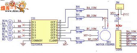
Learning the working principle and controlling methods of stopper motor and mastering some simple circuit-control and basic motor knowledge.
The Stepper Motor Control Experimental Circuit is shown below.
(View)
View full Circuit Diagram | Comments | Reading(1090)
Using TX05D Infrared Control Door Bell Circuit
Published:2011/5/12 23:43:00 Author:Robert | Keyword: Infrared Control, Door Bell
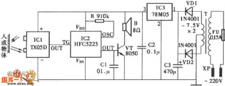
The Using TX05D Infrared Control Door Bell Circuit is shown below.
(View)
View full Circuit Diagram | Comments | Reading(1063)
| Pages:262/312 At 20261262263264265266267268269270271272273274275276277278279280Under 20 |
Circuit Categories
power supply circuit
Amplifier Circuit
Basic Circuit
LED and Light Circuit
Sensor Circuit
Signal Processing
Electrical Equipment Circuit
Control Circuit
Remote Control Circuit
A/D-D/A Converter Circuit
Audio Circuit
Measuring and Test Circuit
Communication Circuit
Computer-Related Circuit
555 Circuit
Automotive Circuit
Repairing Circuit