
Index 264
Holiday color light with disco sound circuit
Published:2011/5/16 9:41:00 Author:Christina | Keyword: Holiday color light, disco sound circuit
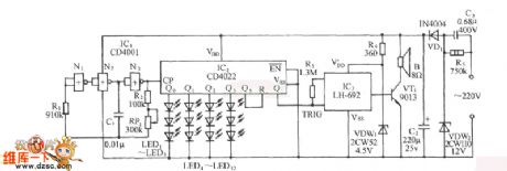
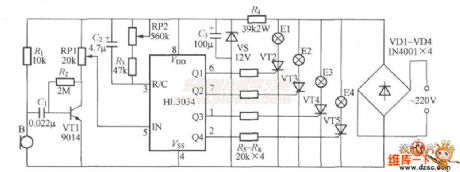
The circuit is as shown. It is composed of the clock pulse generator, the counter / divider circuit, the disco analog sound circuit and the AC step-down rectifier circuit.etc.
(View)
View full Circuit Diagram | Comments | Reading(1255)
ultrasonic repeling mosquito device
Published:2011/5/16 9:38:00 Author:Christina | Keyword: ultrasonic, repeling mosquito
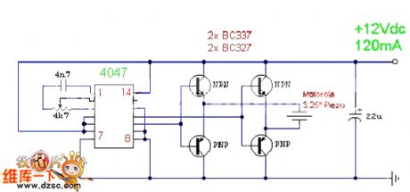
The ultrasonic ultrasonic repeling mosquito device
This is one kind of extremely simple ultrasonic repeling midge, bug, cockroach circuit.
This relaxation oscillation circuit is composed of the CMOS 4047 monostable trigger, you can make it's center frequency to 22KHz by adjusting the 4K7, then the signal is output by the bridge type power which is composed of four transistors to promote the 3.25 inch Piezo to send out ultrasonic signal. (View)
View full Circuit Diagram | Comments | Reading(1353)
Practical 3-button interlock electronic switch circuit
Published:2011/5/16 18:50:00 Author:Christina | Keyword: Practical, 3-button, interlock, electronic switch
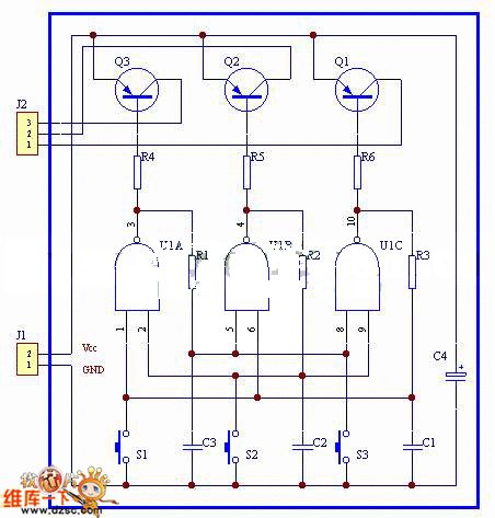
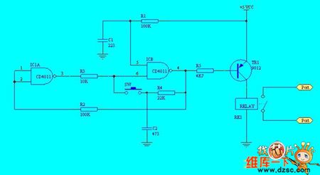
The circuit structure is simple, when you press any key, the corresponding channel opens. And the contact point's jitter does not affect the circuit's working, so this circuit has the good anti-interference performance.
If you remove the rear driver transistor, the circuit's static power consumption is nearly zero.
If you remove the button, this circuit can be used to control the pulse. (View)
View full Circuit Diagram | Comments | Reading(1097)
Amplifier circuit uses the frequency to control the gain
Published:2011/5/16 9:07:00 Author:Christina | Keyword: Amplifier, frequency, gain
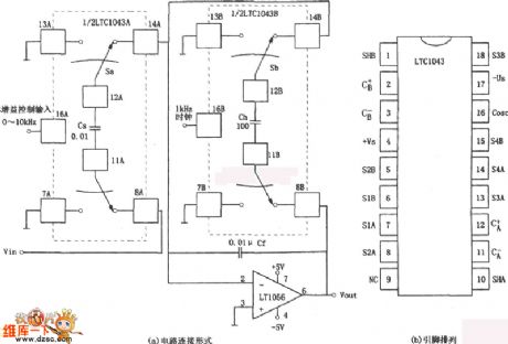
The amplifier circuit that uses the frequency to control the gain is as shown. Frequency gain control circuit uses the different input clock frequencies to control the amplifier gain. As the figure (a) shows, this circuit is composed of two parts: the analog switch and the integrated amp. The analog switch is composed of two pieces of the precise capacitance switch LTC1043; the integrated operational amplifier uses the JFET input op amp type LT1056.
(View)
View full Circuit Diagram | Comments | Reading(632)
Low Power AC/DC General Motor Thyristor Control Circuit
Published:2011/5/18 19:32:00 Author:Robert | Keyword: Low Power, AC/DC, General, Motor, Thyristor, Control
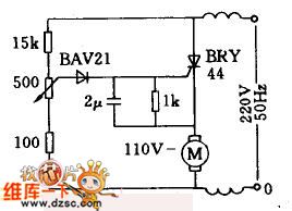
This circuit is used in the case of AC/DC general series wound motor stepless speed variation. Armature winding is in series with field winding through the thyristor. By the single-phase half-wave phase-shifting commutating control method, the thyristor's control angle could be changed by adjusting the 500ω potentiometer. So it can make the rotate speed be stepless adjusted from zero to the maximum value. This circuit is widely used in small household appliances such as blenders, sewing machines, hand drills and woodworking machinery.
(View)
View full Circuit Diagram | Comments | Reading(3739)
DC Motor Driving Circuit
Published:2011/5/18 10:03:00 Author:Robert | Keyword: DC Motor, Driving
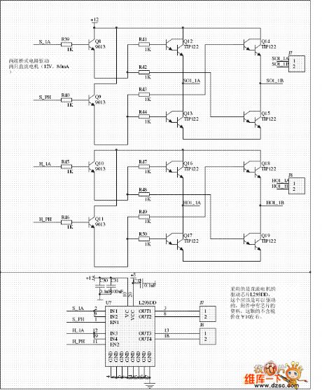
The DC Motor Driving Circuit is shown below.
These are two DC motor driving circuit, one is driven by electric bridge while the other is driven by integrated circuit L293DD, which is used to drive two DC motor (12V, 80mA). On the other hand, for L293DD input port,maybe it can make the IN1, IN2 (IN3, IN4) connected toghter separately and controlled by a MCU port.
(View)
View full Circuit Diagram | Comments | Reading(1641)
Stepper Motor General Driving Circuit
Published:2011/5/18 7:17:00 Author:Robert | Keyword: Stepper Motor, General, Driving
The Stepper Motor General Driving Circuit is shown below.
The integrated system uses small type stepper motor, which is not highly required on voltage and current. Tointroduce the application principle, this circuit uses the simplest driving circuit which aiming at verifying the use of stepper motor. When using in normal industrial control it needs to improve from this base model. General driving circuit can shown in picture as follow.
(View)
View full Circuit Diagram | Comments | Reading(592)
Small Electric Heater Temperature Control Circuit Composed Of Three-Wire Serial Interface Smart Temperature Sensor DS1620
Published:2011/5/18 7:08:00 Author:Robert | Keyword: Electric Heater, Temperature Control, Three-Wire, Serial, Interface, Smart, Temperature Sensor
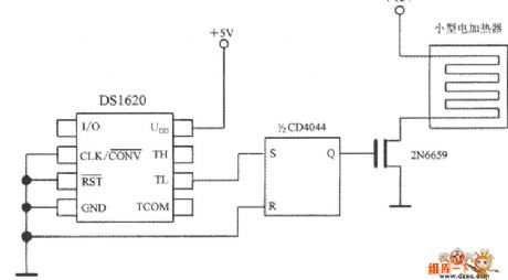
The Small Electric Heater Temperature Control Circuit Composed Of Three-Wire Serial Interface Smart Temperature Sensor DS1620 is shown in the picture below. When t<tL, TL would output high voltage level, which would set the 1/2CD4044 type RS trigger to be 1 and Q=1. This wouldmake the TMOS FET 2N6659 connected and also make the small electric heater's power connected. The 2N6659's UDSO=35V and PD=6.25W.
(View)
View full Circuit Diagram | Comments | Reading(2758)
Two-Wire Serial Interface Smart Temperature Sensor TCN75 And 89C51 MCU Interface Circuit
Published:2011/5/18 6:49:00 Author:Robert | Keyword: Two-Wire, Serial, Interface, Smart, Temperature Sensor, MCU
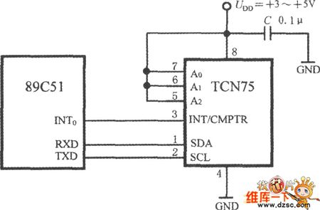
The interface circuit of TCN75 and 89C51 is shown in the picture below. Byletting the TCN75's address input ports A2~A0 all connect to high voltage level UDD, the address code is changed to be 111. The 89C51 can achieve the chip-selection function by software. The 89C51's series data receiving port (RXD) and series data transmitting port (TXD) are connected to the TCN75's SDA port and SCL port separately. TCN75's interrupt/compare signal is connected to 89C51's interrupt port INT0.
(View)
View full Circuit Diagram | Comments | Reading(1147)
Motor electronic governor controller 5
Published:2011/5/17 21:07:00 Author:Nicole | Keyword: Motor, electronic governor controller
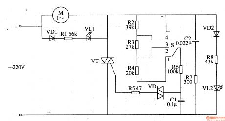
The circuit work theory
This motor electronic governor controller circuit is composed of SCR VT, diode VD1, VD2, bidirectional trigger diode VD, LED VL1, VL2, capacitors C1, C2, resistors R1-R8, speed regulation switch S and motor M, the circuit is shown in the figure 8-62.
When the speed regulation switch S gear is changed, the charge-dischange rate of capacitor C is changed, then the SCR VT conduction angle is changed too. The voltage on both sides of C1 will trigger and turn on VT by VD, the AC voltage on both sides of motor M can be changed by changing the conduction angle of VT, then M's running speed is changed too.
(View)
View full Circuit Diagram | Comments | Reading(2600)
Motor electronic governor controller 4
Published:2011/5/17 20:41:00 Author:Nicole | Keyword: Motor, electronic governor controller
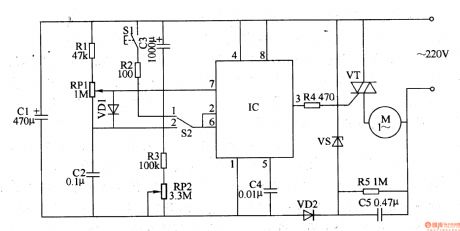
The circuit work theory
This motor electronic governor controller circuit is composed of power supply circuit, time control/trigger pulse generator circuit and control implement circuit, the circuit is shown in the figure 8-61.
The power supply circuit is made of depressurization capacitor C5, steady voltage diode VS, rectifier diodes VD2, filter capacitors C1.
The time control/trigger pulse generator circuit consists of time base integrated circuit IC, control switch S1, timing/voltage regulation selection switch S2, resistors R1-R3, potentiometers RP1, RP2, capacitors c2-c4.
The control implement circuit is composed of resistor R4 and SCR VT.
(View)
View full Circuit Diagram | Comments | Reading(3231)
fast inverting amplifier with high input impedance circuit
Published:2011/5/15 2:33:00 Author:John | Keyword: fast inverting amplifier
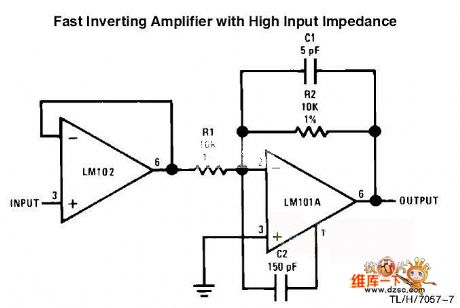
Fast inverting amplifier with high input impedance circuit is shown below.
(View)
View full Circuit Diagram | Comments | Reading(1216)
Music type refrigerator door closing reminder circuit
Published:2011/5/16 8:40:00 Author:Christina | Keyword: Music type, refrigerator, door closing, reminder
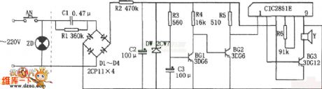
The Music type refrigerator door closing reminder circuit is as shown. This circuit is composed of the step-down rectifier voltage-stabilizing circuit, the delay circuit, the music IC CIC2851E, the speaker.etc. The step-down rectifier voltage-stabilizing circuit supplies the 3V DC voltage to the whole circuit.
When you open the door of fridge, switch AN connects. and the capacitor C3 is charged through R3, BG1's base potential rises, after about 20 minutes delay, C3's voltage makes BG1 conduction, and makes the BG2 cut-off, and this voltage triggers the CIC2851E to work, the output music signal is amplified by BG3 and drives the speaker Y to send out the music of ling er xiang ding dang.... to remind the master to close the door quickly.
(View)
View full Circuit Diagram | Comments | Reading(1086)
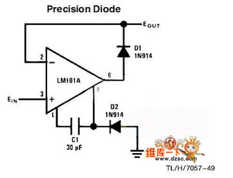
precise diode circuit
Published:2011/5/15 6:19:00 Author:chopper | Keyword: precise diode
View full Circuit Diagram | Comments | Reading(753)
Single button switch circuit
Published:2011/5/17 5:07:00 Author:chopper | Keyword: Single button, switch
View full Circuit Diagram | Comments | Reading(629)
Four Line Light Control Circuit
Published:2011/5/17 8:20:00 Author:Robert | Keyword: Four Line, Light, Control
The Four Line Light Control Circuit is shown below.
(View)
View full Circuit Diagram | Comments | Reading(723)
Water Temperature Automatically Control Device Circuit
Published:2011/5/17 7:22:00 Author:Robert | Keyword: Water Temperature, Automatically Control Device
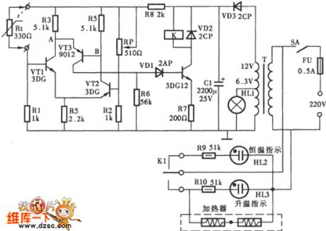
The Water Temperature Automatically Control Device Circuit is shown below.
(View)
View full Circuit Diagram | Comments | Reading(1288)
Op amp power supply voltage polarity reverse protection circuit diagram
Published:2011/5/17 3:21:00 Author:Rebekka | Keyword: Op amp, power supply voltage, polarity reverse protection
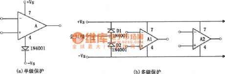
The protection circuit of the op amp power supply reverse polarity is shown in figure (a), (b). Figure (a) is protection circuit of the single-stage amplifier, Figure (b) is the multi-stage amplifier circuit protection circuit. If the integrated operational amplifier without power polarity protection. The power supply voltage polarity is reversed, a destructive current will pass the chip (usually when the chip is in normal operation, there will be a large current passes the reverse-biased diode). The principle of the protection circuit is very simple. For figure (a), it uses the one-way conductive of the diode, so that the reversed power supply voltage can not be added to the integrated operational. For figure (b), it is concentrated protection circuit. When the power supply voltage is reversed, the diodes D1 and D2 turns on. (View)
View full Circuit Diagram | Comments | Reading(1670)
Op amp power supply over-voltage protection circuit diagram
Published:2011/5/17 3:44:00 Author:Rebekka | Keyword: Over-voltage protection , Op amp power supply
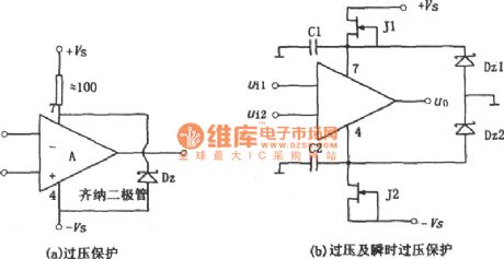
Power supply over-voltage protection circuit is shown as above. Figure (a) is simple and practical over-voltage protection circuit, which uses Zener diode Dz to limit the integrated operational amplifier supply voltage within the safe voltage limit. The selection method of the regulator of the operating voltage can be based on the following formula: Vz ≤ 2Vsmax. Normally Vz should be close or equal to the total power supply voltage, its current limiting resistor R should use high-power resistance, and resistance value should ensure the voltage regulator tube is able to work properly. Figure (b) shows the two functions that overvoltage protection and transient voltage protection. When it is in normal operation mode, the tube pressure of J1 and J2 should be decrease, ± VSD value is low, so the two regulators Dz1 and Dz2 do not work, so none of them is breakdown. (View)
View full Circuit Diagram | Comments | Reading(1988)
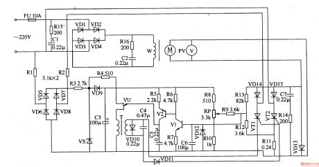
Motor electronic governor controller 1
Published:2011/5/17 1:45:00 Author:Nicole | Keyword: motor, electronic governor, controller
The circuit work theory
This motor electronic governor controller circuit is composed of power supply circuit, excitation circuit, trigger circuit and speed governing control circuit, the circuit is shown in the figure 8-58.
The power supply circuit is made of fuse FU, resistors R1-R3, rectifier diode VD5-VD9, voltage stabilizing diode VS and filter capacitor C3.
The excitation circuit consists of resistors Rl5, Rl6, capacitors C1, C2 and diodes Dl-D4.
The trigger control circuit is composed of pulse transformer T, unijunction transistor VU, transistors V1, V2, diode VDlO-VDl2, capacitors C4-C6 and resistors R4-R7.
(View)
View full Circuit Diagram | Comments | Reading(2680)
| Pages:264/312 At 20261262263264265266267268269270271272273274275276277278279280Under 20 |
Circuit Categories
power supply circuit
Amplifier Circuit
Basic Circuit
LED and Light Circuit
Sensor Circuit
Signal Processing
Electrical Equipment Circuit
Control Circuit
Remote Control Circuit
A/D-D/A Converter Circuit
Audio Circuit
Measuring and Test Circuit
Communication Circuit
Computer-Related Circuit
555 Circuit
Automotive Circuit
Repairing Circuit