
Index 272
SG201 leakage protection IC diagram
Published:2011/5/9 2:23:00 Author:Ecco | Keyword: leakage protection , IC
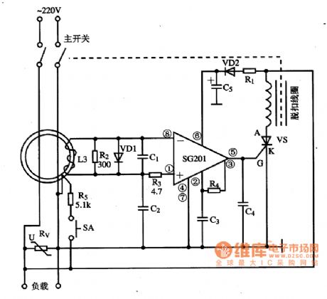
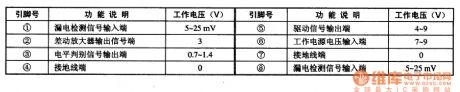
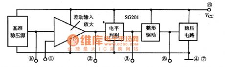
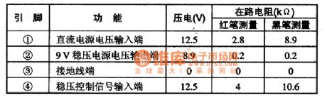
SG201 is the specific leakage protection integrated circuit, which is widely used in a variety of leakage protection. 1. Features of functionsSG201 IC includes voltage regulator circuit, reference voltage circuit, the differential amplifier circuit, level judging and shaping output circuit, the internal block circuit diagram is shown as the chart. 2. Pin functions and data SG201 integrated circuit uses 8-pin dual in-line package, the pin functions and data are listed in table. Operating current is 1.8 ~ 2.5mA, so the static power consumption is low. 3. The typical application circuit The typical application circuit of SG201 IC leakage protection circuit is shown in Figure 1.
(View)
View full Circuit Diagram | Comments | Reading(1017)
Simple temperature control circuit
Published:2011/5/9 19:00:00 Author:TaoXi | Keyword: Simple, temperature control
The Simple temperature control circuit (View)
View full Circuit Diagram | Comments | Reading(464)
lOW sound and light siren circuit diagram
Published:2011/5/6 4:24:00 Author:Ecco | Keyword: lOW, sound , light s, iren

lOW sound and light siren circuit diagram is shown as the chart. The circuit can produce high-intensity alarm which can be used as anti-theft alarm. When the power is switched on the alarm system, VD1 is flashing, while it outputs the pulse square wave on R1 resistor, after gets triangular wave by passing R2, VD2, C1 network, IC is a 555 time base circuit, and it forms voltage-controlled oscillator. R3, R4 and C3 are the timing components. The output variable tone signal is amplified by the VT under the control of the triangular wave to promote the speaker, the output power closes to l0W. Adjusting R1 can change the triangle wave amplitude of C1, changing W1 can adjust the volume. Figure (b) is printed installation diagram.
(View)
View full Circuit Diagram | Comments | Reading(1569)
Household constant temperature control circuit
Published:2011/5/9 18:45:00 Author:TaoXi | Keyword: Household, constant temperature control
The Household constant temperature control circuit is as shown: (View)
View full Circuit Diagram | Comments | Reading(429)
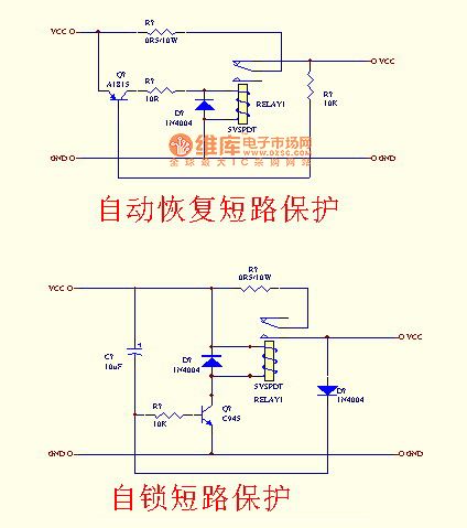
Short-circuit protection circuit with relay
Published:2011/5/9 4:13:00 Author:Rebekka | Keyword: Short-circuit protection , relay
View full Circuit Diagram | Comments | Reading(3805)
Frost Alarm Circuit
Published:2011/5/8 6:45:00 Author:Robert | Keyword: Frost, Alarm
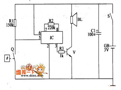
In the natural disasters, the frost's damage to crops is very serious which can have a direct impact to crop yield.The frost alarm circuit introduced in this picture, can have the alarm sounds when the environmental temperature is lower than 1℃ to remind the farmers to prepare for anti-forst in time.The circuit's working principle is shown below.This frost alarm circuit is made up by power circuit, temperature monitoring control circuit and alarm circuit which is shown in the picture below. The power circuit is made up be battery GB, power switch S and electron-contact thermometers Q.The alarm circuit is made up by the sound effect integrated circuit IC, resistance R2, R3, transistor V and speaker BL.When the power switch S is connected, the alarm circuit is in alert mode. When the environmental temperature is higher than 1℃, the Q's electrical thermal control contactor is disconnected and the alarm circuit is not working and BL has no sound. When the environmental temperature decrease to 1℃ or less, the Q's electrical thermal contactor is connected to trigger the IC to work. The sound effect electrical signal from the IC's 3 foot is amplified by V to drive the BL to play the alarm sound.V uses 59013 or CW9561 type sound effect integrated circuit.
(View)
View full Circuit Diagram | Comments | Reading(904)
Hall device series connection drive circuit diagram
Published:2011/5/6 2:26:00 Author:Nicole | Keyword: Hall device, series connection
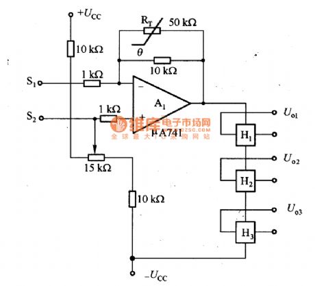
The figurea is a hall device series connection drive circuit. Hall device's magnetoresistance effect produces error. In the circuit, it adopts the method of H1, H2, H3 hall devices series connection, it eliminates the error which is produced by magnetoresistance effect by adding negative feedback. The thermal resistor RT which is connected to feedback circuit is used to improve the circuit's temprature characteristice. S1 and S2 are used in the input motor's turn speed control singal.
(View)
View full Circuit Diagram | Comments | Reading(755)
PQO9RD11 controllable voltage regulator integrated circuit diagram
Published:2011/5/6 4:27:00 Author:Rebekka | Keyword: Controllable voltage regulator , integrated circuit
PQO9RD11 is a controllable voltage regulator integrated circuits. It is widely used in large screen color TV. PQO9RD11 is integrated circuit 4-pin single row package, the pin functions and data of IC are listed in Table 1.Table 1 shows the pin function and data of PQO9RD11 integrated circuit. (View)
View full Circuit Diagram | Comments | Reading(1665)
Constant temperature control circuit compose of the smart temperature sensor DS1620 with three-wire serial interface
Published:2011/5/8 22:38:00 Author:Christina | Keyword: Constant temperature, smart temperature sensor, three-wire serial interface
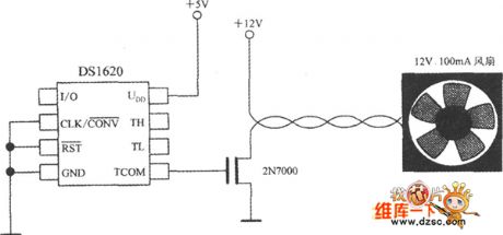
When you use the DS1620 to monitor the temperature of the microprocessor, you can change the chip's cooling condition by turn on or off the fan to achieve the temperature control, the circuit is as shown. The feature is: the TCOM signal gets through the 2N7000-type MOSFET to control the fan, when the chip's surface temperature is t>tH, the fan turns on until t<tL. The main parameters of the 2N7000 are: the drain-source breakdown voltage UDSO=60V, the rated on-state current IT=280mA, the maximum continuous output power PD=830mW. For the high power cooling fan, you can use the 2N7010-type MOSFET, it's IT=13A,PD=1.2W.
(View)
View full Circuit Diagram | Comments | Reading(1275)
TA872OAN multi-channel electronic switch integrated circuit
Published:2011/5/6 21:45:00 Author:TaoXi | Keyword: multi-channel, electronic switch
The TA872OAN is designed as one kind of multi-channel electronic switch integrated circuit that can be used in all kinds of video and audio equipment as the multi-channel signal switch.
1.Features
The TA872OAN has the multi-channel electronic switch circuit and the multi-channel 6dB amplifier to amplify the transmitted signals to 6db then sends the signals to the post-stage circuit.
2.Pin functions and data
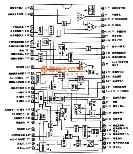
The TA872OAN can be used in large screen color TV as the TV/AV (S-VHS) electronic switch, the pin functions and data is as shown in table 4. This IC uses the 30-pin plastic dual in-line structure. The internal conversion circuit is divided into two parts, the video part and the audio part, it has the noise reduction function, and it is controlled by the signals from the single-chip microcomputer.
Table 1 TA869OAN, TA8691AN in-circuit block diagram, thepin functions and data
(View)
View full Circuit Diagram | Comments | Reading(1398)
TA8776N surround sound analog integrated circuit
Published:2011/5/6 4:04:00 Author:TaoXi | Keyword: surround sound, analog
The TA8776N is designed as one kind of surround sound analog integrated circuit that is produced by the TOSHIBA company, and it can be used in the TV audio system
and home theater sound system.
1. TA8776N in-circuit block diagram and the pin functions
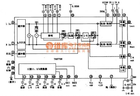
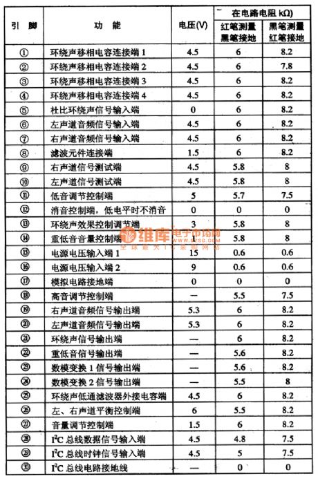
The TA8776N's manifold-circuit is controlled by the I2C-bus, and it can control the audio volume, increase the high pitch, increase the low pitch, adjust the left and right channels, surround sound switch, bass switch and control the volume. The in-circuit block diagram is as shown in figure 1. This IC is in the 30-pin double-row type package, the pin functions and data is as shown in table 1.
Figure 1 The in-circuit block diagram
Table 1 The pinfunctionsanddata of the TA8776N
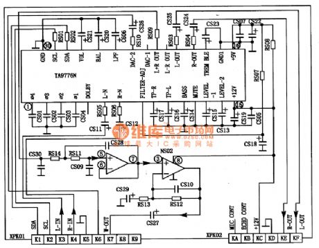
2. The typical application circuitof the TA8776N
The typical application circuitof the TA8776N is as shown in figure 2.
3. The circuit working process
(1)Volume control. The volume control signal of the microprocessor is processed by the TA8776, and forms the DC voltage to control the internal attenuator. Higher the pin (27)'s voltage is, louder the volume is.
(2)Left and right balance control. Left and right balance control signals of the microprocessor form the DC voltage in pin-26. The control law is same to above.
(3)High, low bass control. Bass boost control signal of the microprocessor forms the DC voltage in pin-11. High pitch boost control signal forms the DC voltage in pin-18.4. Troubleshooting Tips (View)
View full Circuit Diagram | Comments | Reading(4402)
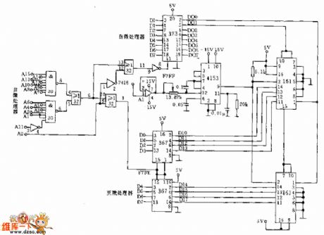
Digital frequency meter course design circuit
Published:2011/5/8 19:19:00 Author:Christina | Keyword: Digital frequency meter, course design
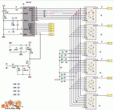
Figure. The digital frequency meter course design circuit (View)
View full Circuit Diagram | Comments | Reading(1879)
Digital voltmeter signal circuit
Published:2011/5/8 19:13:00 Author:Christina | Keyword: Digital voltmeter, signal circuit
View full Circuit Diagram | Comments | Reading(652)
Music volume control (LF356) circuit
Published:2011/5/6 21:23:00 Author:TaoXi | Keyword: Music volume
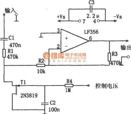
The Music volume control (LF356) circuit is as shown. This circuit can be used in Kara OK audio equipment and it also can be used to control the microphone music volume automatically and weak the base music. FET T1 (2N3819) can be used as the variable resistor, R1 and T1 constitute the divider circuit, T1's equivalent resistance is controlled by the control voltage of T1's control gate, the gate control voltage is amplified and rectified, filtered by the audio signal. This control voltage changes with the input signal, and the partial pressure ratio of the input signal changes too, that changes the music signal components which are sent into the op amp inverting input port. This circuit uses the FET input-type integrated operational amplifier LF356. As the circuit is the inverse proportion operation, so the input resistance is small (less than 470kΩ), the half-power bandwidth is about 5Hz ~500kHz, the gain range is 0~-38dB, the input signal amplitude should not exceed 8Vp-p.
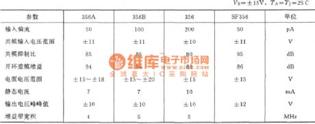
The main parameters of the integrated operational amplifier LF356 (typical):
(View)
View full Circuit Diagram | Comments | Reading(1805)
Electronic code lock circuit
Published:2011/5/8 19:01:00 Author:Christina | Keyword: Electronic, code lock
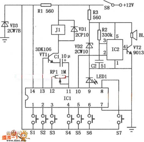
The electronic code lock circuit is as shown.
The ICl is the 5G058-specific lock integrated circuit 5G058, it's pin 1 to pin-6 connect the external key switches to the power positive supply, they are six valid input key, if you want to unlock it, you must comply with the order of Sl to S6; key switch S7 is the false key input port which is connected to pin-8, it is free to connect one or several keys into a keyboard; pin-9 is the key direction port, during each key connectivity, the LEDl will turn on to confirm that the key input is valid; pin-10 is the alarm output port, if you do not comply with the order of Sl to S6 or exceed the effective unlock time, pin-10 will output the high-level voltage to trigger the IC2 anti-burglar alarm language circuit SR8803A and make the speaker BL to issue the language warning. The effective unlock time is determined by the sizes of capacitor C1 and potentiometer RPl.
Figure . Electronic code lock circuit (View)
View full Circuit Diagram | Comments | Reading(1514)
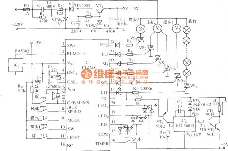
Using PT2128/PT2268 function remote control fan circuit diagram
Published:2011/4/8 3:02:00 Author:Rebekka | Keyword: function remote control , fan circuit
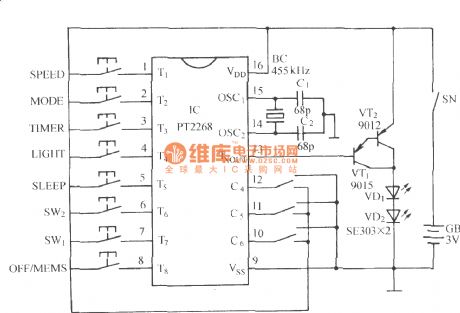
PT2268 remote control encoder transmitter circuit:
PT2128 Lantern Musicvariable speed fan control circuit:
(View)
View full Circuit Diagram | Comments | Reading(3328)
SCR Dimmer Circuit used for 230V Incandescent lamps
Published:2011/4/28 18:44:00 Author:Christina | Keyword: 230V Incandescent, SCR Dimmer
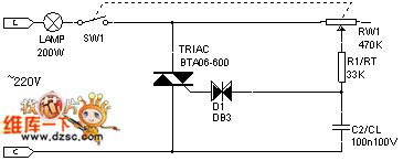
1.The basic model traic dimmer
2.The practical model traic dimmer
3.The minimum brightness adjustable traic dimmer
In most cases, we hope the minimum brightness of the bulb will be stable after sw1 close-up, so access r2 in this circuit can achieve this purpose. If we change r2 to the variable resistor, the adjustment will be more accurate.
4.Withthe light-steady function dimmer
When the ambient light changes, resistance value of cds will be change too, this value will be changes the conduction angle of traic, makes lamp1 changes the brightness in the opposite direction. And the rw2 is used to adjust the sensitivity of cds.
5.Stable adjustment dimmer
6.Dimmer of eliminate the lag effect
(View)
View full Circuit Diagram | Comments | Reading(1789)
Connect with the motor phase failure-protection voltage relay circuit
Published:2011/5/3 6:17:00 Author:Christina | Keyword: motor, phase failure-protection, voltage relay circuit
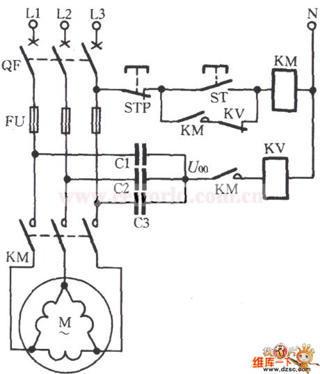
For the △ connection motor, we must make an artificial neutral point (connect three equivalent capacitances (resistance component) as the Y-shaped) with the motor, and connect the relay and other protective devices to this Y-shaped mid-point, as the figure shown. When the three-phase power motor works, the neutral point voltage U00 is less than 10V. When the motor load outage, the neutral point voltage is related with the load, and the range is 10 ~ 50V, heavier theload is, higher the voltage is, but it has little connection with the capacity of the motor. If we use the DJ131/60CN type voltage relay (voltage range is 15 ~ 60V, coils in series and the long-term permissible voltage 220V is 220V), operation voltage can be set at 20 ~ 25V; if the motor load is below 50% to 60%, the tuning voltage is 15 ~ 20V. If the motor has the △ connection, the man-made Y-shaped impedance element can use the 0.1 ~ 0.47μF, 400V capacitor. This circuit is suitable for the 0.6 ~ 55kW motor. (View)
View full Circuit Diagram | Comments | Reading(3717)
Blanking Automatic Adjustment Circuit
Published:2011/5/3 6:21:00 Author:Christina | Keyword: Blanking, Automatic Adjustment
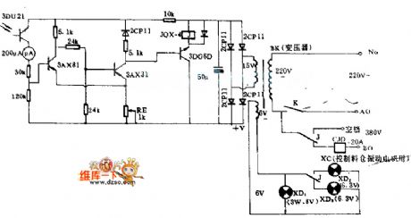
The hot mill machine which can be used to manufacture the fibreboard, it mills the pieces of wood into fiber pulp, the wood falls from the silo into hot mill machine's feed port channel, the channel has this device. When the wood falling into the feed port channel, and the wood stack height is lower than a certain range, this device controls the hopper vibrator automaticly to let the wood falls down. If the wood stack height is higher than a certain range, this device closes the hopper vibrator to achieve the purpose of automatic control.
(View)
View full Circuit Diagram | Comments | Reading(621)
Mains supply overvoltage protection circuit with good performance
Published:2011/4/18 9:56:00 Author:Nicole | Keyword: mains supply, overvoltage protection

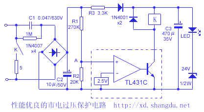
In electric power lacking areas, the power supply is very unstable, the peak value is only about 170V, at night, it is over 250V, in order to protect the expanding household appliances, it is needed to deploy a overvoltage protector.
The circuit is as shown, it adopts capacity depressurization and simple regulated power supply circuit, when the power supply is normal, the TL431C control pole voltage is lower than 2.5V, TL431C circuit is not conductive, realy contact is open. When the mains power reached 250V, after rectifier filter, the current is 3.3mA, the voltage drop on R3, diode and regulator tube(including LED) is 11V and 26V. 37V voltage is divided by R1, R2, then A point voltage is 2.55V, TL431C circuit turns on, relay K pull-in, mains power is a short circuit, then the power supply over current device is tripping or fuse burn-out, it can protect household appliances. To series connect a small resistance in contact loop, it can protect contact from burning off due to the overlarge short-circuit current. Because the capacitance of capacitor C3 is larger, it can store large charge to add on the relay coil, then the relay contact will keep 0.2s pull-in time, it is enough to make over current device trip or fuse burn-out.
(View)
View full Circuit Diagram | Comments | Reading(2337)
| Pages:272/312 At 20261262263264265266267268269270271272273274275276277278279280Under 20 |
Circuit Categories
power supply circuit
Amplifier Circuit
Basic Circuit
LED and Light Circuit
Sensor Circuit
Signal Processing
Electrical Equipment Circuit
Control Circuit
Remote Control Circuit
A/D-D/A Converter Circuit
Audio Circuit
Measuring and Test Circuit
Communication Circuit
Computer-Related Circuit
555 Circuit
Automotive Circuit
Repairing Circuit