
Index 276
telephone auto transponder circuit
Published:2011/5/3 19:25:00 Author:Christina | Keyword: telephone, auto transponder
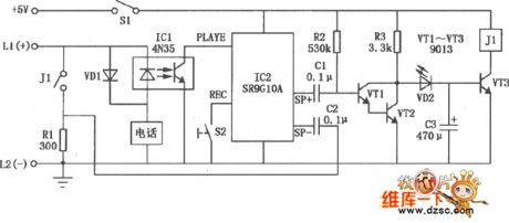
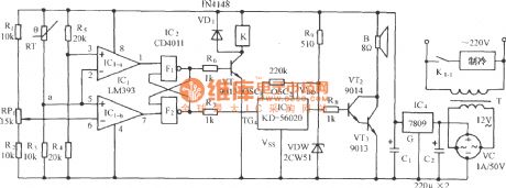
The telephone auto transponder circuit is as shown in figure. IC2 is the 10 seconds voice recording circuit SR9G10A, if you press S2 to open the power, so you can entry the words which you want to tell your friends by the IC2's electret microphone. If you press Sl before go out for walk, the composite pipe's(is composed of the transistor VTl, VT2) electrode voltage VCE will be 0.65V, and the diode VD2 and transistor VT3 will not conduct.
When a call comes in, the phone ring's negative half cycle of ringing signal makes the ICl Optocoupler 4N35 conduction, IC2's PLAYE port is connected to ground to playback, one channel of the unilateral audio signal is amplified by the composite pipe to make transistor VT2's VCE increased, VD2, VT3 will conduct and relay JI will close to make the resistor Rl connects the external analog telephone (telephone's DC resistance is 300Ω); the other channel of unilateral audio signal adds to both ends of the telephone line, so your friends can hear your voice. After the sound finished, the circuit backs to the static state, relay J1 releases and the whole circuit is equivalent the hook.
(View)
View full Circuit Diagram | Comments | Reading(760)
Phone hang-up voice reminder circuit
Published:2011/5/3 9:36:00 Author:Christina | Keyword: Phone hang-up, voice reminder
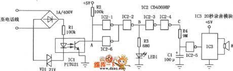
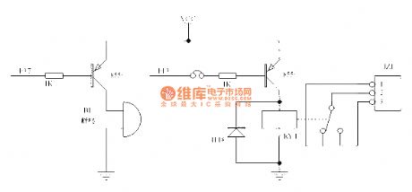
With the increasing of living space, many families install some telephone extensions in different rooms, but the phone always can not be dialed in because one of the telephone extension does not hang. The phone hang-up voice reminder circuit is as shown, it can automatically issues the sound of call is not hung, please check the extensions to remind the user check the extensions.
(View)
View full Circuit Diagram | Comments | Reading(930)
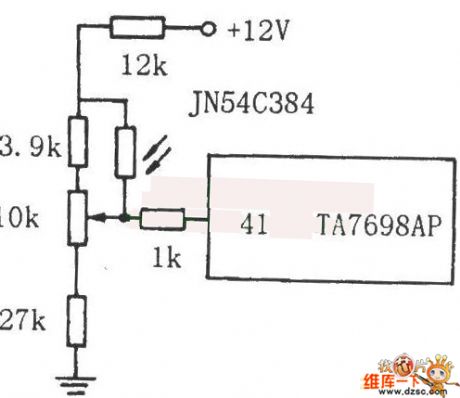
Diagram of TV brightness auto-regulate circuit using photosensitive resistance
Published:2011/5/3 7:42:00 Author: | Keyword: TV, brightness, auto-regulate circuit, photosensitive resistance,
View full Circuit Diagram | Comments | Reading(559)
laser transmitter linearity control circuit diagram
Published:2011/5/3 8:01:00 Author: | Keyword: laser, transmitter, linearity control
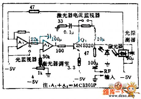
Using optics feedback technology can keep invariable laser output inawide temperature change range.This circuit is a optics negative feedback that is not sensentive to temperture range.
(View)
View full Circuit Diagram | Comments | Reading(645)
Promote the FET with the transformer circuit
Published:2011/5/3 7:36:00 Author:Christina | Keyword: FET, transformer
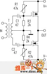
This circuit uses the transformer to promote the FET and has no big negative feedback loop, it is simple to debug and you can try to use it.
(View)
View full Circuit Diagram | Comments | Reading(477)
precise variable-frequency oscillator circuit
Published:2011/5/3 7:23:00 Author:Christina | Keyword: precise, variable-frequency, oscillator
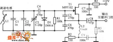
The precise variable-frequency oscillator circuit is as shown:
(View)
View full Circuit Diagram | Comments | Reading(1376)
Motor reversing control circuit diagram
Published:2011/5/3 3:07:00 Author:Rebekka | Keyword: Motor reversing control
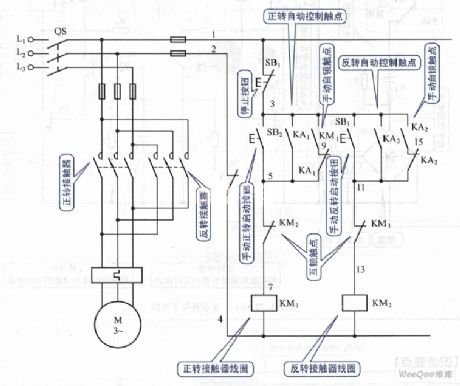
Motor reversing control circuit diagram. (View)
View full Circuit Diagram | Comments | Reading(955)
Circuit of Simple Production of Wireless Headphones
Published:2011/5/3 2:56:00 Author:Felicity | Keyword: Circuit of Simple Production of Wireless Headphones,
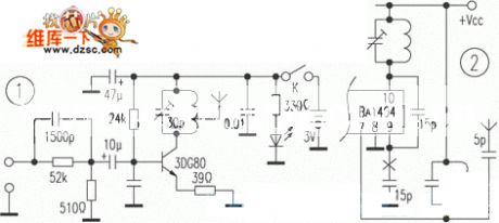
Circuit of Simple Production of Wireless Headphones is showed in the picture above. (View)
View full Circuit Diagram | Comments | Reading(783)
Electromagnetic speed governing control circuit diagram
Published:2011/5/3 3:01:00 Author:Rebekka | Keyword: Electromagnetic, speed governing control
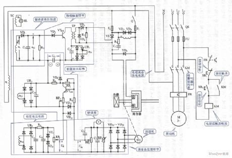
Electromagnetic speed governing control circuit diagram. (View)
View full Circuit Diagram | Comments | Reading(1761)
Steam pressure switch control circuit diagram
Published:2011/5/3 2:31:00 Author:Rebekka | Keyword: Steam pressure switch control
Steam pressure switch control circuit diagram. (View)
View full Circuit Diagram | Comments | Reading(1943)
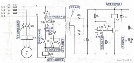
Extraction type water level control circuit diagram
Published:2011/5/3 2:30:00 Author:Rebekka | Keyword: Extraction type , water level control
Extraction type water level control circuit diagram. (View)
View full Circuit Diagram | Comments | Reading(1264)
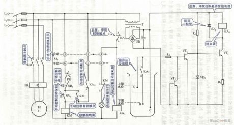
Water towers and reservoirs linkage control circuit diagram
Published:2011/5/3 2:28:00 Author:Rebekka | Keyword: Water towers , reservoirs linkage
Water towers and reservoirs linkage control circuit diagram. (View)
View full Circuit Diagram | Comments | Reading(772)
SCM buzzer relay circuit
Published:2011/5/3 1:41:00 Author:TaoXi | Keyword: SCM, buzzer relay
The SCM buzzer relay circuit is as shown:
(View)
View full Circuit Diagram | Comments | Reading(645)
The protection circuit diagram composed of negative resistance leds
Published:2011/5/3 1:33:00 Author:Ecco | Keyword: protection circuit , negative resistance , led
View full Circuit Diagram | Comments | Reading(585)
Open circuit, short circuit anti-theft alarm circuit diagram
Published:2011/5/2 22:55:00 Author:Ecco | Keyword: Open circuit, short circuit , anti-theft , alarm circuit
AC driving light-emitting diodes can make higher output optical power, the driving circuit form is shown as the chart. The two LEDs are connected reversely in parallel, so that the positive and negative half-cycle of power have a light-emitting diode to display. (View)
View full Circuit Diagram | Comments | Reading(1151)
Using ER1211 ASIC as automatic exposure control circuit diagram
Published:2011/5/2 20:53:00 Author:Rebekka | Keyword: ASIC, automatic exposure control
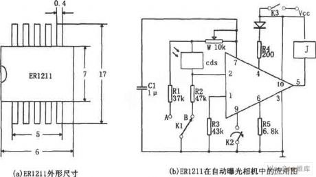
The figure shows the diagram of using ER1211 ASIC as automatic exposure control circuit. ER1211 is the automatic exposure control ASIC in the automatic camera. The pin arrangement is shown in Figure (a), ① is the supply voltage monitoring, ② is the illumination monitoring, ③ is grounding, ④ is illumination warning output, ⑤ is relay drive output, ⑥ is exposure time delay device, ⑦ is exposure delay input, ⑧Automatic focus control, ⑨ is exposure control, ⑩ is power Vcc. When the shutter button is in the mode of half-pressed K2. If illumination environment light is lower than limit (V2 ≤ V6-0.2V), ④ pin outputs low level, low-light warning light LED light. Linkage with the flash K-selector switch is opened at the receiving position A, the corresponding C1 pass W, R1 to discharge, the exposure time (discharge time) is fixed, even if the flash automatic metering circuit does not work.
(View)
View full Circuit Diagram | Comments | Reading(825)
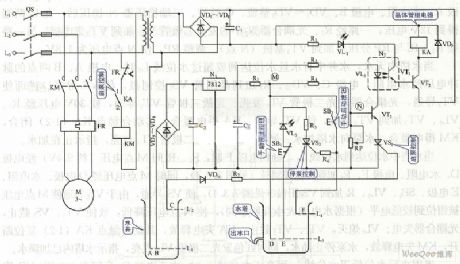
Thermal resistor temperature control refrigeration birdsong phonation circuit
Published:2011/4/29 21:24:00 Author:Nicole | Keyword: thermal resistor, temperature control refrigeration, birdsong
The circuit is as shown, it consists of temperature detection circuit, power ON/OFF detection circuit, relay control motor circuit, birdsong phonation circuit and AC depressurization rectifier circuit. It keeps the temperature of the freezer within the setting temperature range, and it will send out a dulcet small bird sound. (View)
View full Circuit Diagram | Comments | Reading(1207)
Clock control timing start-up obfuscation guard against theft acousto-optic control circuit
Published:2011/4/29 4:34:00 Author:Nicole | Keyword: clock control, guard against theft, acousto-optic control
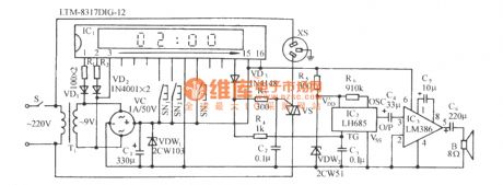
The circuit is as shown. It is composed of clock control timing circuit, SCR control circuit, voice phonation circuit, audio power amplifier circuit and AC depressurization rectifier circuit. This circuit is used for relics exhibition hall, temple, mosque and those occasionsoccasions when nobody is on guard during night. Before the watch keeper leaving,they shouldpreset the clock control time, such as 2:00 am. When it is the preset time, the circuit will light up the indoor lights automatically, and send out noice, to create a false impression that there is someone on duty, then to puzzle the prowler, so that the perpetrator will not rush prematurely. (View)
View full Circuit Diagram | Comments | Reading(779)
Three key interlock electronic switching circuit diagram
Published:2011/5/2 21:08:00 Author:Rebekka | Keyword: Three key interlock, electronic switching
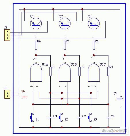
Three key interlock electronic switching circuit diagram. (View)
View full Circuit Diagram | Comments | Reading(1012)
Municipal electric power photoelectric control circuit
Published:2011/5/2 7:41:00 Author:Nicole | Keyword: Municipal electric power, photoelectric control
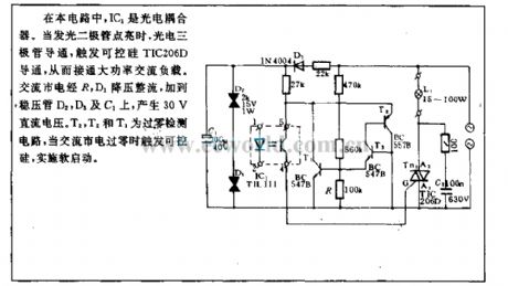
In this circuit, IC1 is photoelectric isolator. When LED is lightened, photoelectric triode turns on, to trigger SCR toturn on, then to connect the high power AC load. AC municipal electric power is added to regulator tube D2, D3 and C1 through R, D1 depressurization rectifier, it will produce 30V DC voltage. T2, T3 are zero-crossing detection circuit, when the AC municipal electric power is zero-crossing, it will trigger SCR to do soft start. (View)
View full Circuit Diagram | Comments | Reading(878)
| Pages:276/312 At 20261262263264265266267268269270271272273274275276277278279280Under 20 |
Circuit Categories
power supply circuit
Amplifier Circuit
Basic Circuit
LED and Light Circuit
Sensor Circuit
Signal Processing
Electrical Equipment Circuit
Control Circuit
Remote Control Circuit
A/D-D/A Converter Circuit
Audio Circuit
Measuring and Test Circuit
Communication Circuit
Computer-Related Circuit
555 Circuit
Automotive Circuit
Repairing Circuit