
Index 287
Delay light circuit with TRIAC(2)
Published:2011/4/20 2:44:00 Author:Nicole | Keyword: Delay light, TRIAC
View full Circuit Diagram | Comments | Reading(1249)
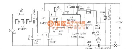
Delay light circuit with TRIAC(3)
Published:2011/4/20 2:43:00 Author:Nicole | Keyword: Delay light, TRIAC
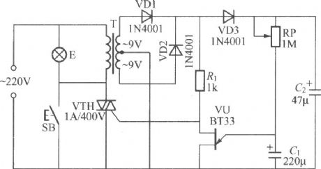
The circuit is as shown, it is a delay light circuit adopts TRIAC, T uses 220V/9V×2、3VA small transformer, there is no special requirements about other components. (View)
View full Circuit Diagram | Comments | Reading(1793)
Delay light circuit with digital circuit(2)
Published:2011/4/20 2:12:00 Author:Nicole | Keyword: delay light, digital circuit
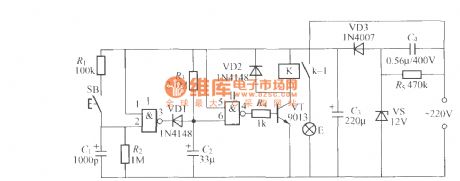
The figure is as shown, it is a delay light circuit adopts 2 input terminals and negation gate digital IC, VD3、VS、 C3、C4 form a simple capacity depressurization half wave rectifier steady voltage circuit, after connecting to power supply, two terminals of C3 will output about 12V stable DC voltage to provide the whole controller. Gate Ⅰ, gate Ⅱ, can adopt two good NAND gates of CD4011 digital IC, the input terminals of another NAND gates should be connected to ground, to avoid interference. K uses JZC-22F、DC12V small middle power electromagnetic relay. (View)
View full Circuit Diagram | Comments | Reading(563)
Delay light circuit with digital circuit(3)
Published:2011/4/20 1:56:00 Author:Nicole | Keyword: delay light, digital circuit
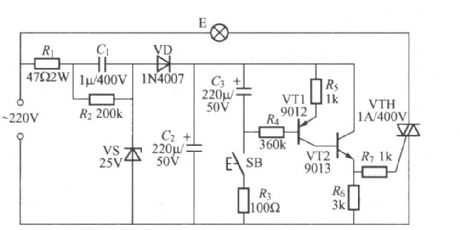
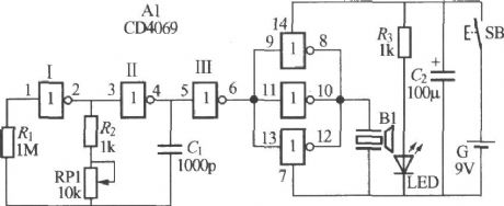
The figure is as shown, it is a practical delay light circuit, it can be used in nightstand. The feature of it is to press the key SB, the light on; press it again, the light off; if it does not press SB after the light on, the light will delay few minutes, then the light off automatically; after the light off, if you press switch two times constantly, the light will on again. This delay light is convenient to work, and it can add spices. According to T=0.639R3C2, we can obtain the delay time, but the C2 has electricity leakage, so the delay time is increased to 30~50min. (View)
View full Circuit Diagram | Comments | Reading(537)
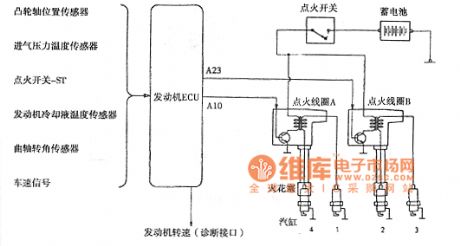
Saima car ignition system circuit
Published:2011/4/20 2:45:00 Author:Jessie | Keyword: car ignition system
View full Circuit Diagram | Comments | Reading(464)
Ultrasonic remote control dimming light receiver
Published:2011/4/20 1:30:00 Author:Nicole | Keyword: ultrasonic remote control, dimming light
Ultrasonic transmitter circuit:
Ultrasonic remote control dimming receiver circuit:
B1、B2 adopt well-assorted TCT40-12F2 and TCT40-12F2 piezoelectric ceramics ultrasonic transducer. (View)
View full Circuit Diagram | Comments | Reading(2020)
Night automatic light circuit with TRIAC
Published:2011/4/20 2:39:00 Author:Nicole | Keyword: automatic light, TRIAC
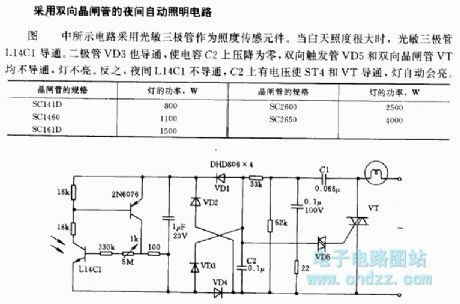
The circuit is as shown, it adopts phototransistor as illuminance sensor. In daytime with high illuminance, the phototransistor L14C1 turns on. Diode VD3 turns on too, then the pressure drop on capacitor C2 is zero, bidirectional trigger VD5 and TRIAC VT are all off, the light is not on. On the contrary, at night L14C1 turns off, C2 has voltage to make ST4 and VT turn on, the light will light automatically. (View)
View full Circuit Diagram | Comments | Reading(1415)
The motor vehicle headlight auto-dimming controller 9
Published:2011/4/19 21:54:00 Author:Ecco | Keyword: motor vehicle , headlight, auto-dimming , controller
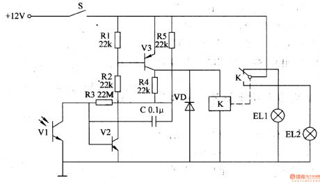
The working principle.The vehicle headlight auto-dimming controller circuit consists of phototransistor Vl, transistors V2 and V3, resistor Rl-R5, capacitor C, diode VD and relay K, the circuit is shown as the figure 7-9.
S is headlamp switch of car, EL2 is the internallow beam light of headlamp, ELlis the high beam. V2 and V3forms a Schmitt trigger circuit.
When driving at night, turning on S, + l2V voltage is added to the high beam by the normally closed contact of S and K, so that the EL2 islit.
When meeting other cars, the light exposure from the opposite traveling car will make the conduction ability of V1and V2 increase, V3 turns on, K gets power and pulls in, the normally open contact isconnected, high beam ELl turns off,low beamEL2 turns on.
After meeting cars, the internal resistance of V1 will increaseas it has no light exposure,the conduction ability of V2 decreases, V3 is cut off, K releases, the normally closed contact is connected, normally open contact is disconnected, ELl turns on,low beamEL2 turns off.
C is a positive feedback circuit, which makes Schmitt trigger circuit delay.
R1-R5 choose 1/4W metal film resistors or carbon film resistors.
C chooses monolithic capacitors or polyester capacitor.
VD uses lN4007 silicon rectifier diode.
K selects a l2V 4098 DC relay.
(View)
View full Circuit Diagram | Comments | Reading(1492)
The motor vehicle headlight auto-dimming controller
Published:2011/4/19 21:04:00 Author:Ecco | Keyword: motor vehicle, headlight , auto-dimming , controller
The working principle.
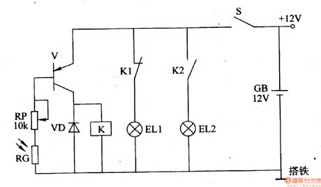
The vehicle headlight auto-dimming controller circuit consists of photoresistor RG, potentiometer Rp, transistor V, diode VD and relay K, the circuit is shown as the figure 7-8.
When driving at night, turning on the headlamp switch S, RG is in the high impedance state when no light exposure, V cuts off, K isin releasing state, the normally closed contact Kl is connected, the normally open contact K2 is off, the internal high beam ELl of headlamp is lit, low beam EL2 is off.
When meeting other cars at night, the internal resistance of RC will decrease as the light exposure from the opposite traveling car, V will be saturated and conducted, K gets power and pulls in, the normally closed contact is disconnected, normally open contact is connected, the high beam ELl turns off, the low beam EHL2 turns on, that realizes the auto-dimming control. After meeting other cars, RG is in high impedance state, V cuts off, K releases, and the headlight automatically restores the upper light state.
RG usesMG45 seriesphotosensitive resistor.
RP uses small multi-turn potentiometers or variable resistor with carbon film synthesis.
VD uses lN4007 silicon rectifier diode.
V uses S8550 PNP transistors.
K selects a l2V JRX-l3F or JQX-4 DC relay.
(View)
View full Circuit Diagram | Comments | Reading(1681)
The motor vehicle headlight auto-dimming controller 7
Published:2011/4/19 21:23:00 Author:Ecco | Keyword: motor vehicle, headlight , auto-dimming , controller
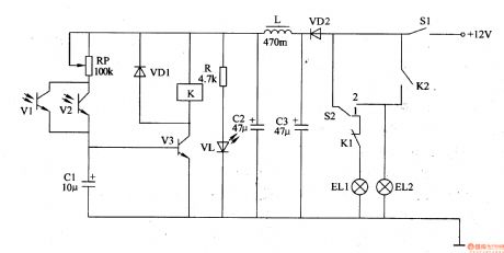
The motor vehicle headlight auto-dimming controller described in the example can automatically change the high beam into low beam at night, it does not need the driver to change the light by hand, and improve thesafety of driving at night.The working principle.The vehicle headlight auto-dimming controller circuit consists of power supply filter circuit and the light control circuit, the circuit is shown as the figure 7-7.
The power supply filter circuit is composed of isolation diode VD2, filter capacitor C2 and C3, inductor L, current limiting resistor R and light-emitting diode VL.
Light control circuit consists of photosensitive transistors Vl and V2, diodes VDl, potentiometer RP, capacitor Cl, transistors V3 and the relay K.
When driving at night, the power switch S1 is connected, +12 V voltage isprovided for control circuit afterfiltering. Light control switch S2 will be set to 1 (high beam) position, the high beam light ELl is lit,low beam EL2 is not lit.
R chooses 1/4W metal film resistor or carbon film resistors.
RP selects a small variable resistor or organic solid potentiometer.
Cl-C3 selects an electrolytic capacitor with thevoltagein 16V.
L selects a core fixed inductor with the current greater than 500mA.
K selects a l2V4098 DC relay. (View)
View full Circuit Diagram | Comments | Reading(708)
The motor vehicle headlight auto-dimming controller 6
Published:2011/4/19 21:38:00 Author:Ecco | Keyword: motor vehicle , headlight, auto-dimming , controller
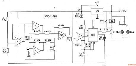
The motor vehicle headlight auto-dimming controller described in the example can work alternately between the state of 1·9S high beam and low beam when driving at night. It will automatically become low beam when meeting other cars, it has a better dimming effect.
he working principle.The vehicle headlight auto-dimming controller circuit consists of voltage regulator, light control amplifier, and controlling implementation of the multivibrator circuit, the circuit is shown as the figure 7-6.
The voltage regulator circuit consists of three-terminal voltage regulator integrated circuit IC4, diode VD2 and filter capacitor C2.
The light control amplifier is composed of photocell GB, operational amplifier integrated circuit ICl (Nl-N4), IC2 (N5), resistors Rl-R8 and potentiometer RPl, RP2.
The multivibrator circuit is composed of time-base integrated circuit IC3, resistors R9, RlO, capacitors Cl, C3.
The controlling implementation is composed of resistors Rll, the transistor V, Relay K and diode VD3.
Rl-Rll choose 1/4W metal film resistor or carbon film resistors.
RP1 and RP2 choose sealed membrane variable resistors.
K selects a l2V JRX-l3F DC relay.
Gb selects small-capacity silicon photovoltaic cell.
(View)
View full Circuit Diagram | Comments | Reading(1400)
Gain 1~8000 times programmable amplifier circuit with PGA203
Published:2011/4/19 22:16:00 Author:Jessie | Keyword: Gain 1~8000 times, programmable, amplifier
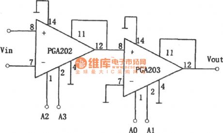
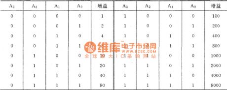
As shown is gain 1~8000 times programmable amplifier circuit. This circuit uses PGA202, PGA203 integrated chips. TheNC gain range of PGA202 is 1, 10, 100 and 1000. And theNC gain range of PGA203 is 1, 2,4 and 8.The corresponding relation of gain control terminals A2 (pin 1), A3 (pins 2) and the gain is listed in table below. (View)
View full Circuit Diagram | Comments | Reading(711)
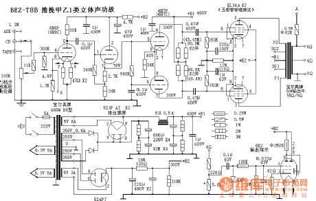
Push-pull AB class 1 stereo amplifier BEZ-T8B circuit
Published:2011/4/20 1:32:00 Author:Jessie | Keyword: AB class 1, stereo amplifier
View full Circuit Diagram | Comments | Reading(1206)
LC172 acousto-optic dual control 4-phase pulse distribution color lamp control circuit
Published:2011/4/20 0:24:00 Author:Nicole | Keyword: acousto-optic dual control, 4-phase pulse, color lamp
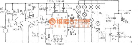
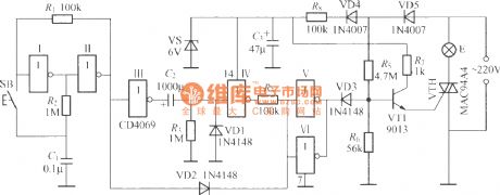
The circuit is as shown. It is composed of audio amplifier, acousto-optic dual control switch, light control circuit and AC depressurization rectifier circuit. 4-phase pulse distribution light control special IC LC172 is made as the core to consist the light control circuit. (View)
View full Circuit Diagram | Comments | Reading(643)
AC color lamp control circuit composed of LC181 audio modulation color lamp control chip
Published:2011/4/19 21:56:00 Author:Nicole | Keyword: AC color lamp, control chip
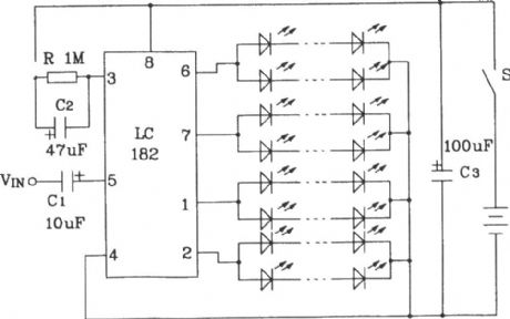
The cycle frequency is 0.5~1Hz. LED cycles flashing slowly. When connected the audio modulation singal, the cycle speed of LED will change with the audio singal, if the cycle frequency is 1Hz, then the highest modulation rate is more than 15 times. To change the value of RC, it can change the cycle speed without modulation singal. This circuit is suitable for all kinds of artwares, vases, painted screen and so on. (View)
View full Circuit Diagram | Comments | Reading(588)
Incandescent lamp life extension switch circuit(5)
Published:2011/4/19 21:43:00 Author:Nicole | Keyword: incandescent lamp, life extension

The figure is as shown, it is another connection way of the incandescent lamp life extension switch, it has two functions: one is it can start up with half wave depressurization when it is connected to the power supply, then it will turn into total pressure feeding after the filament preheats enough; the other is this circuit will transfer to half wave depressurization feeding automatically, once the mains power network voltage is 20V higher than the 220V standard voltage, it can delay the service life of incandescent lamp effectively. (View)
View full Circuit Diagram | Comments | Reading(890)
Showcase or bulletin board timing light controllor circuit (2)
Published:2011/4/19 20:35:00 Author:Nicole | Keyword: showcase or bulletin board, timing light, controllor
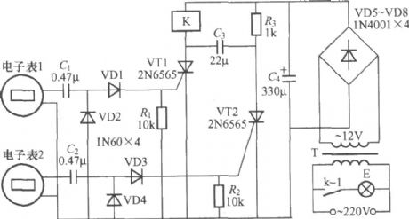
The figure is as shown, it is a showcase or bulletin board timing light controllor adopts two electronic tables control, the electronic table 1 is used to set everyday lighting up time, the electronic table 2 is used to set everyday turn-off light time. K uses small middle power electromagnetic relay such as JZC-22F、DC12V, the maximum load of contact is 5A. (View)
View full Circuit Diagram | Comments | Reading(864)
Timer circuit with monostable free sending device
Published:2011/4/19 20:27:00 Author:Nicole | Keyword: timer, free sending device

The feature of this circuit is the input terminal has anti-interference protection measures, to avoid wrong actions due to the interference signal. Besides, the time process is finished before switch S off, it can increase the reliability. (View)
View full Circuit Diagram | Comments | Reading(567)
High speed bridge mode driver circuit
Published:2011/4/2 4:13:00 Author:may | Keyword: High speed, bridge mode driver
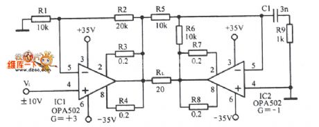
High speed bridge mode driver circuit is shown in the following picture:
(View)
View full Circuit Diagram | Comments | Reading(497)
Sunset light gradual control circuit
Published:2011/4/13 4:17:00 Author:Nicole | Keyword: sunset light, gradually control
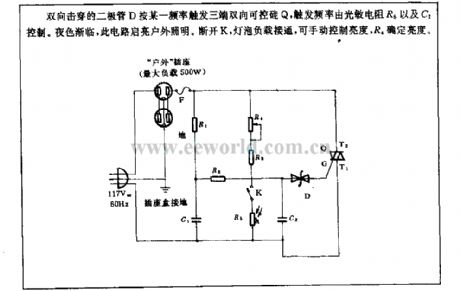
Bidirectional breakdown diode D triggers three terminal TRIAC Q with a frequency, the trigger frequency is controlled by photosensitive resistance R5 and C2. As the night deepened, this circuit starts to outdoor light. To cut off K, then the bulb load turns on, it can manual control brightness, R4 decides the brightness. (View)
View full Circuit Diagram | Comments | Reading(611)
| Pages:287/312 At 20281282283284285286287288289290291292293294295296297298299300Under 20 |
Circuit Categories
power supply circuit
Amplifier Circuit
Basic Circuit
LED and Light Circuit
Sensor Circuit
Signal Processing
Electrical Equipment Circuit
Control Circuit
Remote Control Circuit
A/D-D/A Converter Circuit
Audio Circuit
Measuring and Test Circuit
Communication Circuit
Computer-Related Circuit
555 Circuit
Automotive Circuit
Repairing Circuit