
Index 297
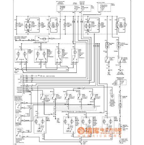
Buick gating lamp circuit
Published:2011/4/10 21:47:00 Author:Jessie | Keyword: gating lamp
View full Circuit Diagram | Comments | Reading(442)
Buick dashboards circuit (ub3)
Published:2011/4/10 21:36:00 Author:Jessie | Keyword: dashboards

View full Circuit Diagram | Comments | Reading(475)
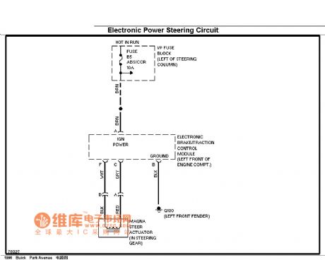
Buick electronic steering circuit
Published:2011/4/10 21:34:00 Author:Jessie | Keyword: electronic steering
View full Circuit Diagram | Comments | Reading(580)
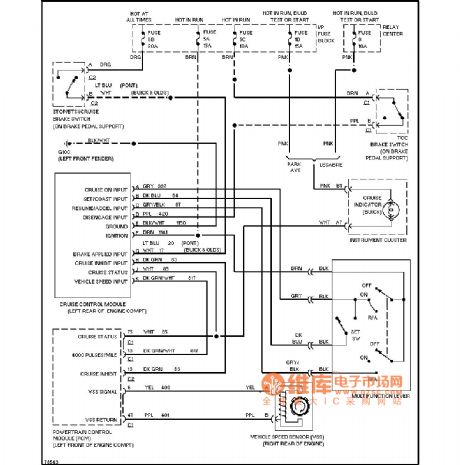
Buick cruise control circuit
Published:2011/4/10 21:18:00 Author:Jessie | Keyword: cruise control
View full Circuit Diagram | Comments | Reading(571)
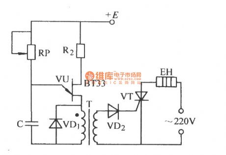
Single junction transistor trigger thyristor by pulse transformer circuit
Published:2011/3/24 3:27:00 Author:Jessie | Keyword: Single junction transistor, trigger thyristor, pulse transformer
View full Circuit Diagram | Comments | Reading(2095)
The principle diagram of IGBT over current protection circuit
Published:2011/4/10 21:50:00 Author:may | Keyword: IGBT, over current protection
View full Circuit Diagram | Comments | Reading(1419)
The application circuit of EXB841
Published:2011/4/10 21:28:00 Author:may | Keyword: application
View full Circuit Diagram | Comments | Reading(1059)
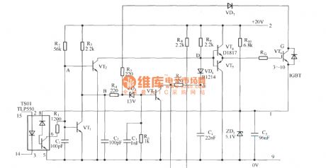
The principle circuit of EXB841
Published:2011/4/10 21:30:00 Author:may
View full Circuit Diagram | Comments | Reading(1874)
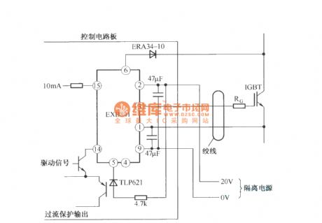
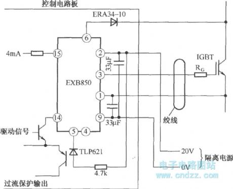
The application circuit of EXB850
Published:2011/4/10 21:31:00 Author:may
View full Circuit Diagram | Comments | Reading(771)
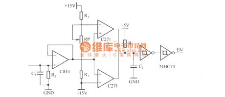
The basic principle of static switch
Published:2011/4/7 22:10:00 Author:may | Keyword: static switch
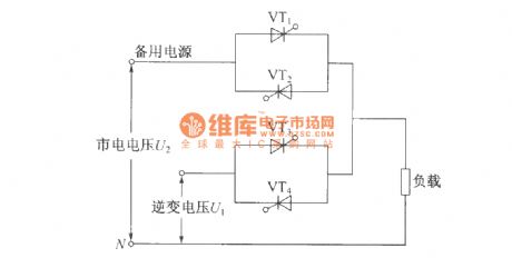
The usage of static switch: it can parallel normal work only when two AC power supply has the same frequency, amplitude. When one AC power supply go wrong, will generate restoring current between the two power supply, thereby make changes of output voltage in two parallel power supply, it will influence the reliable of power supply. The usage of static switch is cut the error power supply to output, and accomplish unbroken switchover between inverter output and commercial power bypass output. We mostly adopts high-speed relay as switching device, because its switching time only has 2ms~5ms, is fit for the requirement of communication equipment needing power supply without interruption. In the case of UPS power supply with capacity above 2KVA, because the increase of relay working current, its switching time will add to 80ms~120ms, and sparkle generated in the moment relay snapping will cause high temperature to damage the contact point, or voltaic arc generated between normal open and normal close contact point will short circuit the two AC power supply in a moment, so relay using for switching is only limit to low capacity UPS power supply, but its switching time has tens seconds. (View)
View full Circuit Diagram | Comments | Reading(3158)
Human body induction alarm circuit diagram
Published:2011/4/6 21:56:00 Author:Rebekka | Keyword: Human body induction, Alarm circuit
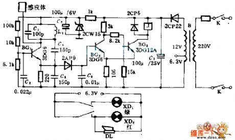
The alarm circuit is a alarm device that makes use of the distributed capacitance of the human body and to work. The multivibrator type oscillator composed of BG1, L1, C1 works but the relay does not before a human body access the alarm; When a human body access the alarm, the periodic circuit will stop work and the alarm will work because of the capacitance of human body. (View)
View full Circuit Diagram | Comments | Reading(1224)
Optical controlling switch circuit using LDR transistor
Published:2011/4/10 21:00:00 Author:Ecco | Keyword: Optical controlling switch , LDR transistor
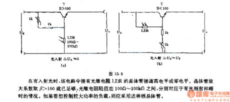
When there's incident light, the LDR in the circuit connects to high level or zero level. The transistor amplification factor βshould be higher than 100, the value of LDR is between 00Ω ~ 100kΩ, they are suitable for bright light and dark shooting situations respectively. If you want to control the high power load, you should adopt Darlington transistors.
(View)
View full Circuit Diagram | Comments | Reading(1502)
Control circuit of a frying pan
Published:2011/3/22 3:18:00 Author:may | Keyword: Control
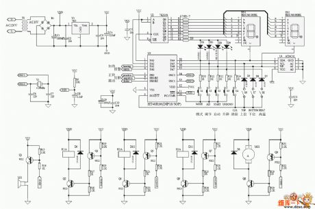
Control circuit of a frying pan is shown in the following diagram:
(View)
View full Circuit Diagram | Comments | Reading(740)
Fan reactor speed controller circuit
Published:2011/3/28 22:40:00 Author:may | Keyword: Fan reactor speed controller
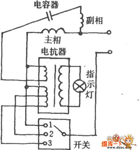
Fan reactor speed controller circuit is shown in the diagram:
(View)
View full Circuit Diagram | Comments | Reading(580)
Motor control circuit diagram braked by three-phase half-wave rectifier
Published:2011/4/10 20:42:00 Author:Ecco | Keyword: Motor control , brakinged , three-phase, half-wave, rectifier
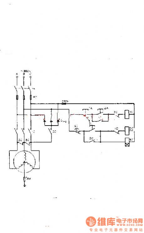
It's motor control circuit braked by three-phase half-wave rectifier, when the AC contactor IC disconnects with the power, 2C, SJ time relays take action immediately, 2X main contact short connects with three winding lead wires of motor and then connects with Three-phase half wave rectifying power supply, then stator windingof motor is connected to parallel symmetrical line of which one end connects to null line. That is to achieve the purpose of braking, and then SJ delayed discinnects, 2C loses electric and releases, the braking ends. The braking lines is suitable for motor star connection, it has the advantages of small volume, low cost and simple lines, but also for larger capacity motor. It's shown as the chart: (View)
View full Circuit Diagram | Comments | Reading(1341)
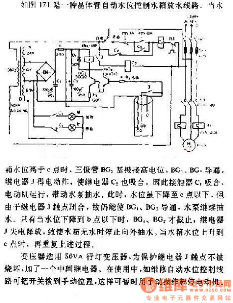
Automatic water level control circuit diagram of draining tank
Published:2011/4/7 21:20:00 Author:Ecco | Keyword: Automatic , water level control, draining tank
View full Circuit Diagram | Comments | Reading(1511)
The school bell timing circuit diagram
Published:2011/4/10 20:20:00 Author:Ecco | Keyword: school bell timing
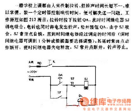
General school bell is pulled by the people, but it is difficult to control the tone time. It can solve this problem by installing a timer to control ring. Working principle is shown in Figure 213: To press the button QA when pulling the bell, the time relay SJ pulls, bell ring tone is also energized, to release the button QA, as the SJ pulls, SJ normally open point is self-hold until time relay seting time(time relay could adjust to 1 minute or according to the choice), the delay normally closed point is cut off and make time relay loses electric and releases, SJ normally open point is cut off, the tone will stop.
(View)
View full Circuit Diagram | Comments | Reading(1012)
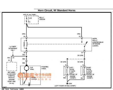
Buick horn circuit (standard configuration)
Published:2011/4/8 2:47:00 Author:Jessie | Keyword: horn
View full Circuit Diagram | Comments | Reading(536)
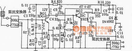
TF903 Super remote antenna amplifier circuit
Published:2011/4/8 4:42:00 Author:Jessie | Keyword: antenna amplifier
View full Circuit Diagram | Comments | Reading(480)
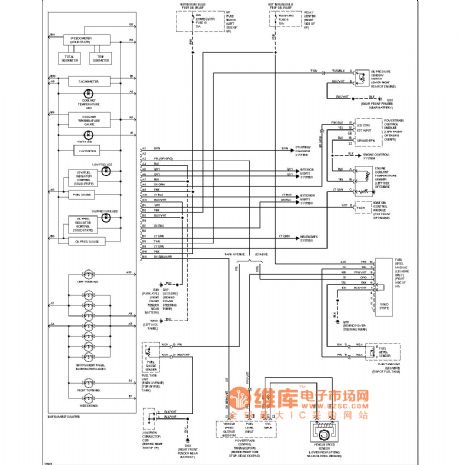
Buick dashboards circuit (instrument, ub3)
Published:2011/4/8 4:43:00 Author:Jessie | Keyword: dashboard
View full Circuit Diagram | Comments | Reading(456)
| Pages:297/312 At 20281282283284285286287288289290291292293294295296297298299300Under 20 |
Circuit Categories
power supply circuit
Amplifier Circuit
Basic Circuit
LED and Light Circuit
Sensor Circuit
Signal Processing
Electrical Equipment Circuit
Control Circuit
Remote Control Circuit
A/D-D/A Converter Circuit
Audio Circuit
Measuring and Test Circuit
Communication Circuit
Computer-Related Circuit
555 Circuit
Automotive Circuit
Repairing Circuit