
Switch Control
Index 14
the op-amp analog switch with high anti-interference ability circuit
Published:2011/6/21 1:35:00 Author:Fiona | Keyword: the op-amp analog switch, high anti-interference ability
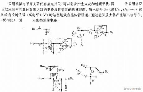
The circuit uses analog electronic switches to replace the node switch to prevent sparking and radio-frequency interference.The picture shows the circuit using junction field-effect transistor and operational amplifier and its equivalent mechanical lines.When the input signal UE (UE1, UE2) has control signal (high 10V) in the B side,the junction field-effect transistor conducts, produces the output signal UA through the operational amplifier. The picture is shown a similar circuit.
(View)
View full Circuit Diagram | Comments | Reading(1209)
Switching Constant-Current Application Circuit Composed Of W723
Published:2011/6/14 23:18:00 Author:Robert | Keyword: Switching, Constant-Current, Application
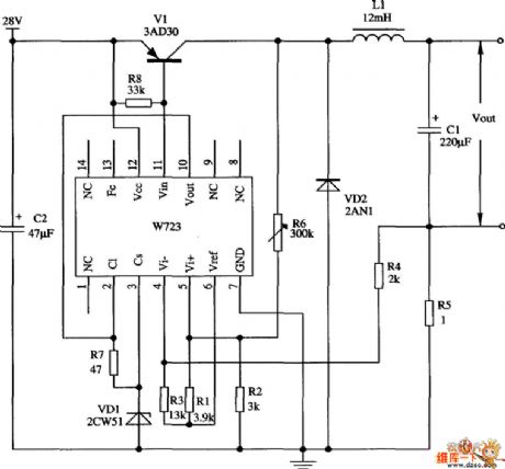
The picture shows the constant-current switching regulator application circuit composed of W723 multi-port adjustable positive regulator. Its output current is 1A. In the circuit in the picture, the R1, R2 would divide the W723's reference voltage (about 7.2V) to about 3V and then add it into the in-phase input port. Also the resistance R3, R4 would divide the reference voltage to add into the out-phase input port. The R4's low port is connected with the current-divider resistance R5. When the out-phase input and in-phase input are nearly balanced, the current-divider resistance R5's voltage drop would be about 1V. R6 is used to adjust the limiting value of output ripple current.
(View)
View full Circuit Diagram | Comments | Reading(1431)
Composed of one-way silicon controlled simple touch switch circuit
Published:2011/6/7 20:01:00 Author:Fiona | Keyword: Composed of one-way silicon controlled
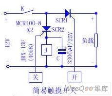
Touch the metal piece to open, SCR1 turns on, the load is energized to work. Touch the metal piece off, SCR2 turns on, the relay J is energized to work,K is off, the load losses the power, SCR2 turns off, the capacitance discharges to the relay J, it keeps the relay pulling in about 4 seconds, so the circuit action is more accurate. If the load replays to the relay, it can control the large current work load. Friends who are interested, give it a try. (View)
View full Circuit Diagram | Comments | Reading(1032)
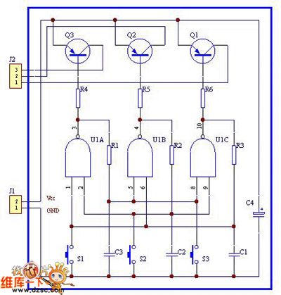
simple and practical three-key interlock electronic switch circuit
Published:2011/5/29 6:58:00 Author:chopper | Keyword: simple and practical, three-key interlock, electronic switch
View full Circuit Diagram | Comments | Reading(862)
SONY KV2184 switch power supply circuit
Published:2011/5/23 22:35:00 Author:John | Keyword: switch
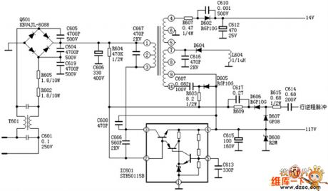
SONY KV2184 switch power supply circuit is shown below.
(View)
View full Circuit Diagram | Comments | Reading(1699)
touch switch delay circuit
Published:2011/5/24 0:13:00 Author:John | Keyword: touch switch
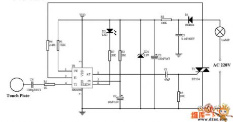
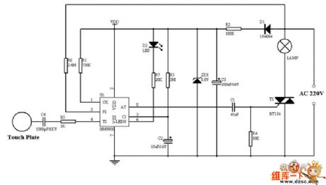
Touch switch delay circuit is shown below.
(View)
View full Circuit Diagram | Comments | Reading(2031)
Street Lamp Automatic Switch Control Circuit
Published:2011/5/12 9:41:00 Author:Robert | Keyword: Street Lamp, Automati, Switch, Control
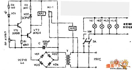
The Street Lamp Automatic Switch Control Circuit is shown below.
(View)
View full Circuit Diagram | Comments | Reading(1088)
CC4052 multi-channel electronic switch integrated circuit diagram
Published:2011/5/9 2:24:00 Author: | Keyword: multi-channel electronic switch
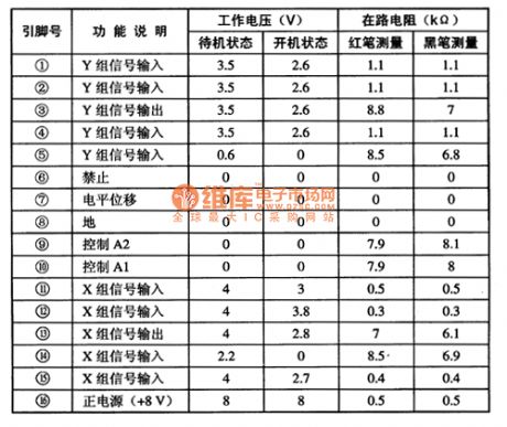
CC4052 is a multi-channel electronic switch integrated circuits produced by Toshiba.It's widely used in audio, video, communications, car audio equipment and the signal switching switch in the other electronic devices.
CC4052 integrated circuits use 16-pin dual in-line package.It is used on changhong CN一15 movement of large screen color TV.The pin functions and data listed in Table 1.
Table 1 CAT2404P integrated circuits' pin functions and data
(View)
View full Circuit Diagram | Comments | Reading(905)
Photocoupler AC switches circuit diagram
Published:2011/5/4 2:01:00 Author:Rebekka | Keyword: Photocoupler AC switches
Photocoupler AC switches circuit diagram. (View)
View full Circuit Diagram | Comments | Reading(700)
Dynamic fit light control AC switches circuit diagram
Published:2011/5/4 1:59:00 Author:Rebekka | Keyword: Dynamic fit light control, AC switches

Dynamic fit light control AC switches circuit diagram. (View)
View full Circuit Diagram | Comments | Reading(829)
Three key interlock electronic switching circuit diagram
Published:2011/5/2 21:08:00 Author:Rebekka | Keyword: Three key interlock, electronic switching
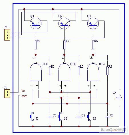
Three key interlock electronic switching circuit diagram. (View)
View full Circuit Diagram | Comments | Reading(1004)
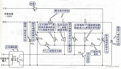
Optical coupling silicon-controlled switch circuit diagram
Published:2011/3/30 22:58:00 Author:Ecco | Keyword: Optical coupling, silicon-controlled switch

The figure 1(a) shows the optical coupling silicon-controlled switch circuitry. The trigger voltage of silicon-controlled rectifier(SCR) is from resistance R, and the the value is decided by the current of phototriode, controlled by input voltage. The circuitry is simple, and there is reliable electronic isolation between the input and output.
The figure 1(b) shows the switching circuitry in which load controll is pure resistance. And the value of R1 in the figure is decided by the formula as below: R1=V/1.2A,1.2A is bidirectional switching rated current. When the voltage of main network is 220V, V=/2·220=308V,then R1=308/1.2=250Ω. So the specification of silicon-controlled rectifier(SCR) is chosed according to the the value of R1.When the load of switching circuitry is inductive, it needs to increase corresponding components to promise the circuitry's normal work, as the current passing the inductive is different from the phase of voltage. It is shown as below: The switching circuitry shown in the figure 2 is especially suitable for distant control.
(View)
View full Circuit Diagram | Comments | Reading(1314)
The frequency selection and sound waves remote control switch circuit of fans
Published:2011/4/6 5:34:00 Author:may | Keyword: frequency selection, sound waves remote control, switch, fans
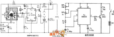
The frequency selection and sound waves remote control switch circuit of fans is shown in the diagram:
(View)
View full Circuit Diagram | Comments | Reading(673)
Multipurpose AC electronic switch circuit (for thermoregulation)
Published:2011/4/6 5:36:00 Author:may | Keyword: Multipurpose, AC electronic switch, thermoregulation
View full Circuit Diagram | Comments | Reading(866)
Multi-controlled three-switch circuit
Published:2011/4/2 4:30:00 Author:may | Keyword: Multi-controlled, three-switch
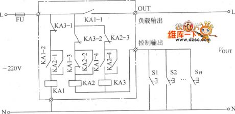
Multi-controlled three-switch circuit is shown in the diagram:
(View)
View full Circuit Diagram | Comments | Reading(611)
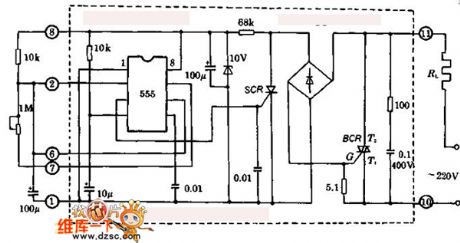
Sub-Ultrasonic Remote Control Switch Circuit
Published:2011/4/27 6:42:00 Author:Robert | Keyword: Sub-Ultrasonic, Remote Control Switch
Sub-Ultrasonic Remote Control Switch Circuit is shown below:
(View)
View full Circuit Diagram | Comments | Reading(628)
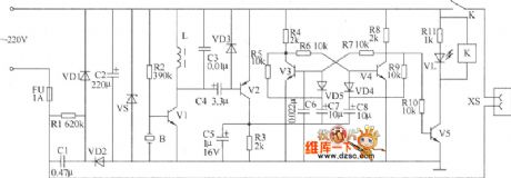
Single-Speed Electric Fan With 40W Ballasts Change To Be Two-Speed Circuit
Published:2011/4/23 9:29:00 Author:Robert | Keyword: Electric Fan, Single-Speed, 40W Ballasts, Two-Speed
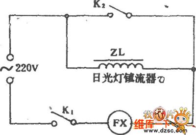
Single-Speed Electric Fan With 40W Ballasts Change To Be Two-Speed Circuit is shown below:
(View)
View full Circuit Diagram | Comments | Reading(657)
Light control alarm circuit diagram
Published:2011/4/14 21:01:00 Author:Ecco | Keyword: Light control, alarm circuit
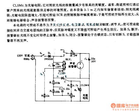
As a photoresistor, CL5M4 has a high sensitivity to the reducing of light exposure. Usually, the light from the street lights can provide enough ambient illumination. If there was an activity to steal the window in 3.1m of the device, the light would be weakened, the resistance of photosensitive resistor and SCR controlling pulse amplitude would increase. Then the SCR starts regenerative amplification, the relay pulls in, the sound alarm warns.
The SCR in the circuit is not used as a switching element. Potentiometer R4 is used to control sensitivity, adjust the R4, to make SCR receive the positive pulse from the AC power, but the pulse amplitude could not make the SCR produce renewable effects. If S2 turns off, the alarm will stop the warning when the light will not change any more. If S2 is closed, the alarm is in self-locking state, the alarm stops warning by cuting off S1.
(View)
View full Circuit Diagram | Comments | Reading(756)
The basic principle of static switch
Published:2011/4/7 22:10:00 Author:may | Keyword: static switch
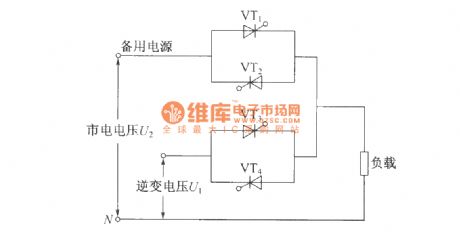
The usage of static switch: it can parallel normal work only when two AC power supply has the same frequency, amplitude. When one AC power supply go wrong, will generate restoring current between the two power supply, thereby make changes of output voltage in two parallel power supply, it will influence the reliable of power supply. The usage of static switch is cut the error power supply to output, and accomplish unbroken switchover between inverter output and commercial power bypass output. We mostly adopts high-speed relay as switching device, because its switching time only has 2ms~5ms, is fit for the requirement of communication equipment needing power supply without interruption. In the case of UPS power supply with capacity above 2KVA, because the increase of relay working current, its switching time will add to 80ms~120ms, and sparkle generated in the moment relay snapping will cause high temperature to damage the contact point, or voltaic arc generated between normal open and normal close contact point will short circuit the two AC power supply in a moment, so relay using for switching is only limit to low capacity UPS power supply, but its switching time has tens seconds. (View)
View full Circuit Diagram | Comments | Reading(3156)
GA series IGBT single switch type module cut-away drawing
Published:2011/4/8 2:08:00 Author:may | Keyword: IGBT, single switch type, cut-away drawing
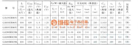
The performance parameter of GA series IGBT single switch type module:
(View)
View full Circuit Diagram | Comments | Reading(935)
| Pages:14/15 123456789101112131415 |
Circuit Categories
power supply circuit
Amplifier Circuit
Basic Circuit
LED and Light Circuit
Sensor Circuit
Signal Processing
Electrical Equipment Circuit
Control Circuit
Remote Control Circuit
A/D-D/A Converter Circuit
Audio Circuit
Measuring and Test Circuit
Communication Circuit
Computer-Related Circuit
555 Circuit
Automotive Circuit
Repairing Circuit