
Switch Control
Index 5
TOUCH_SWITCH_2
Published:2009/7/13 4:31:00 Author:May
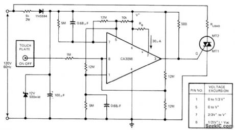
Small AC signal momentarily introduced by finger contact on touch plate causes voltage at pin 8 of CA3098 dual-input precision level detector to be greater than high reference voltage. This toggles memory flip flop in IC, making voltage high at pin 5. Vottage at pin 7 then increases exponentially to V+ in about 10 s.This 10-sdelay is maximumthat button can betouched; longertouch makes system oscillate between ON and OFF states until finger is removed. Shorter touch energizes load, placing pin 7 at V+. Next touch of plate turns circuit off.-G. J. Granieri, Precision Level Detector IC Simplifies Control Circuit Design, EDN Magazine, Oct. 5, 1975, p 69-72. (View)
View full Circuit Diagram | Comments | Reading(0)
MULTIFLASH_SWITCH
Published:2009/7/13 4:20:00 Author:May
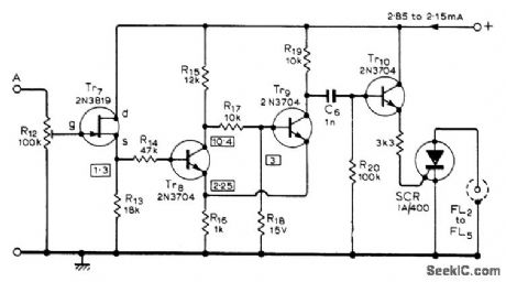
When ramp output of flash trigger circuit (given in article) is applied to input at A, flash at output of switch circuit is tripped when ramp voltage reaches level determined by setting of R12. Similar voltage-operated switches are required for other flashes.Used for taking sequence photographs such as springboard diver in flight. Settings of R12 for diferent switches are chosen for equal times between flashes, with intervals from 11 ms to 11 s. Article gives all circuits and set up procedure.Regulated 19.5-V supply is required-R. Lewis, Multi-Flash Trigger Unit, Wireless World, Nov.1973, p 529-532. (View)
View full Circuit Diagram | Comments | Reading(1022)
GYRO_TORQUING_SWITCH
Published:2009/7/13 3:57:00 Author:May
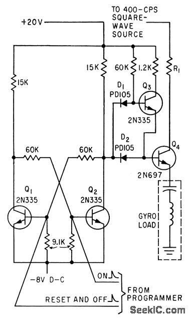
Flip-flop Q1-Q2 controls Q3 driving switching transistor Q4.Trigger signals from telemetry receiver programmer control state of flip-flop. Can pass 400-cps square wave with 10-V peak.-J. H.Porter, Miniaturized Autopilot System for Missiles, Electronics, 33:43, p60-64. (View)
View full Circuit Diagram | Comments | Reading(962)
PROXIMITY_SWITCH
Published:2009/7/13 3:14:00 Author:May
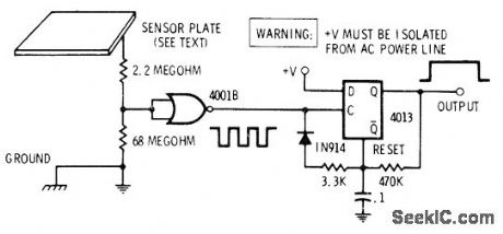
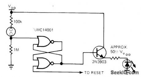
Hand brought near sensor plate induces 60-Hz power-line hum in section of quad two-input NOR gate. Hum is squared bygateand used to trip section of 4013 connected as retriggerable mono MVBR. Output of mono is clean from instant of first proximity until several milliseconds after moving hand away. Sensitivity depends on size of metal plate and on number of permissible false alarms from other noise sources nearby.-D. Lancaster, CMOS Cookbook, Howard W. Sams, Indianapolis, IN, 1977, p 278-282. (View)
View full Circuit Diagram | Comments | Reading(0)
LOGIC_SWITCH
Published:2009/7/13 3:09:00 Author:May
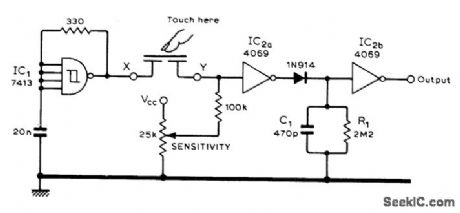
Can be used with batterypowered circuits because CMOS touch switch does not require body pickup of AC Iine hum for switchina action. Schmitt trigger IC1 forms 100 kHz oscillator. IC2a amplifies oscillator output and charges C1 through diode. When sensor is touched, oscillator output is severely attenuated, making C1 discharge and thereby changing output state of level detector IC2b. Sensor is 1-inch-square of double-sided printed-circuit board with lower side divided into two equal sections.-N. Sunderland, C.M.O.S. Touch Switch, Wireless World, May 1978, p 69. (View)
View full Circuit Diagram | Comments | Reading(1176)
LATCHING_TOUCH_SWITCH
Published:2009/7/13 3:05:00 Author:May
Uses LED as status display that substitutes for tactile feel of ordinary pushbutton switch. In reset state, LED is off. When touch contacts are bridged by resistance of finger, flip-flop changes state and LED comes on while output changes to high state.-V. Gregory, CMOS Touch Switches-Convenient, Less $ and Sexy, EDN Magazine, May 5, 1976, p 112. (View)
View full Circuit Diagram | Comments | Reading(1047)
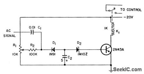
TOUCH_SWITCH_1
Published:2009/7/13 3:03:00 Author:May
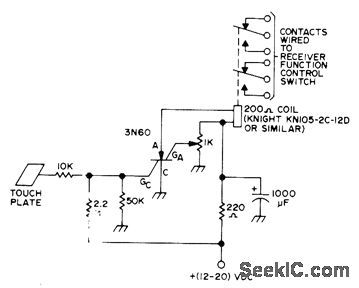
Performs function of switch by means of relay contacts when SCR is triggered by placing finger on touch plate. Values shown keep relay energized for 5-10 s after touch. Developed as replacement for switchtype controls on amateur radio receiver. Once SCR has fired, it conducts until charge on 1000-μF capacitor decreases enough to drop SCR current below minimum for conduction.-J. J. Schultz, Rapid Receiver Control Switching, 73 Magazine, Dec. 1973, p 67-69. (View)
View full Circuit Diagram | Comments | Reading(0)
TOUCH_SWITCH
Published:2009/7/13 3:01:00 Author:May
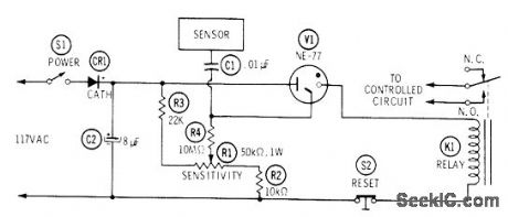
Uses NE-77 neon lamp, which is similar to NE-2 but has third electrode for triggering. When person touches metal sensor plate of switch, AC voltage picked up by body is applied to trigger electrode of neon, making it fire and energize 5000-ohm relay K1 (Potter & Brumfield RS5D or equivalent). Relay remains energized until S2 is opened to reset circuit. Adjust R1 so voltage applied to center electrode of V1 is just below trigger point.-J. P. Shields, How to Build Proximity Detectors & Metal Locators, Howard W.Sams, Indianapolis, IN, 2nd Ed., 1972, p 52-55. (View)
View full Circuit Diagram | Comments | Reading(0)
TOGGLE_SWITCH
Published:2009/7/13 2:49:00 Author:May

Touching one 0.5-inch-square copperclad pattern on printed-circuit board turns switch circuit on by giving high out-put. Touching other plate turns switch off. LED between output and ground shows status of switch. For proper switching, circuit must con nect to line-operated DC power supply.-R. D. Wood, Replace Bulky Mechanical Switches with Touch Controls, EDN Magazine, April20, 1978, p 132-133. (View)
View full Circuit Diagram | Comments | Reading(1154)
DEBOUNCE_FOR_TOUCH_SWITCH
Published:2009/7/13 2:47:00 Author:May
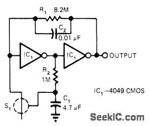
Two CMOS inverters respond to high-impedance path between electrodes of touch switeh to provide finger-touch sensitivity and positive switching action with minimum components. Large time constant of R1C1 requires wait of about 4 s before attempting to retrigger circuit. C2 prevents oscillation from 60-Hz pickup when electrodes are touched.-H. Manell, CMOS lnverters Implement Finger-Touch ON-OFF, EDN Magazine, Jan. 5, 1978, p 90. (View)
View full Circuit Diagram | Comments | Reading(1023)
TOGGLING_TOUCH_SWITCH
Published:2009/7/13 2:45:00 Author:May
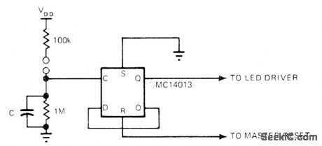
Uses half of Motorola MC14013 as flip-flop that changes state each time contacts are bridged by resistance of finger. For status display, LED driven by 2N3903 transistor can be added. Possible drawback is bouncing if finger is carelessly applied.-V. Gregory, CMOS Touch Switches-Convenient, Less $ and Sexy, EDN Magazine, May 5, 1976, p112. (View)
View full Circuit Diagram | Comments | Reading(875)
Infrared automatic tap controller circuit
Published:2011/8/4 3:29:00 Author:May | Keyword: Infrared, automatic, tap controller
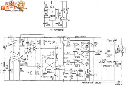
The diagram shows infrared automatic tap controller circuit. This controller circuit includes transmitting circuit and receiveing decoder control circuit. The transmitting circuit is composed of multivibratorand infrared transmitting diode; receiving circuit consists of infrared receiving tubes D1 and D2, operational amplifier IC2(CA741), tone decoder IC3(LM567), AC solid state relay IC4(SP110), power supply circuit and so on.
In the transmitting circuit, multivibrator consists of IC1(555) and R1, R2, C1, etc, and its oscillator frequency f=1.44/(R1+2R2)C1, the corresponding frequency of the parameter isshown in the picture and itis about 40KHz. Oscillator output signal can drive TLN104 LED1~LED3 work to generate infrared pulse modulated wave. (View)
View full Circuit Diagram | Comments | Reading(1634)
1_h_WITH_END_CYCLE_SWlTCH
Published:2009/7/12 22:43:00 Author:May
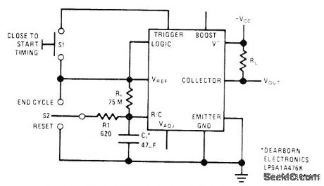
National LM122 timer is connected with manual controls for start, reset, and intermediate termination of 1-h timing cycle started byclosing S1. Once timing starts, S1 has no further effect. Moving S2 up ends cycle prematurely with appropriate change in output state. Moving S2 down resets timing capacitor to 0 V without changing output; releasing S2 starts new timing cycle.-C. Nelson, Versatile Timer Operates from Microseconds to Houm, National Semiconductor, Santa Clara, CA, 1973, AN-97, p 9. (View)
View full Circuit Diagram | Comments | Reading(1067)
SNAP_ACTION_A_F_POWER_LEVEL_SWITCH
Published:2009/7/12 22:21:00 Author:May
When integated voltage reaches point where zener diode breaks from nonconduction to conduction, transistor goes from cutoff to saturation suddenly, to provide fast relay operation.-Snap Action Level Switch, Electronic Circuit Design Handbook, Mactier Pub.Corp. N.Y. p30. (View)
View full Circuit Diagram | Comments | Reading(771)
SCSI_SWITCH
Published:2009/7/12 21:51:00 Author:May
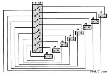
The SCSI switch consists of an eight-position DIP switch, about 24 inches of ribbon cable, and eight female header blocks. A schematic of the switch is shown. The header blocks plug onto the ID pins of the SCSI hard disks. Through the DIP switch, those IDs can be reassigned at will. In any given configuration, whichever physical drive has the lowest SCSI ID becomes the boot drive. The others are allocated in order by SCSI ID. (View)
View full Circuit Diagram | Comments | Reading(846)
TWO_STAGE_SWITCH
Published:2009/7/11 4:43:00 Author:May
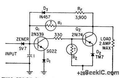
D-c output from carrier amplifer triggers switch consisting of two-stage complementary-coupled nonlinear am pliler, with zener diode in series with input to minimize drift, when difference between two d-c voltages exceeds preset threshold voltages of as little as 100 microvolts for only 300 microsec. Can handle 2 amp. R1 is 100,000 ohms and R2 is 100 ohms.-J. W. Hig-ginbotham and H. H. Douglass, Voltage Comparcttor with High-Speed Switches, Electronics, 32:5, p56--58. (View)
View full Circuit Diagram | Comments | Reading(852)
REMOTE-CONTROLLED_SWITCHER
Published:2009/7/11 3:27:00 Author:May
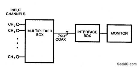
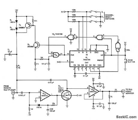


The interface end of Fig. 96-2(a)'s circuit deliver 10 V down the cable, pulses the supply voltage to transmit channel-change commands, and buffers the received video signal.The multiplexer circuit in Fig. 96-2(a) receives power and control signals over the coaxial cable, while driving the cable with the currently selected video signal.The interface circuit (Fig. 96-2(b)) delivers 10 V to the cable and pulses the supply voltage to select one of 8 channels. When the send button is depressed, a digital burst of 1.2 V amplitude (negative) is superimposed on the 12-V line (as a voltage drop). This does not affect the video signal. The multiplexer circuit (Fig. 96-2(c)) consists of a multiplexer and an amplifier. The multiplexer is a Maxim MAX455. The digital code on the supply line is picked off by A1, IC3A, and interfaced to counter IC2, which drives the multiplexer to select the desired video channel. (View)
View full Circuit Diagram | Comments | Reading(1103)
REMOTE_SELECTION_VIDEO_SWITCH
Published:2009/7/11 3:21:00 Author:May
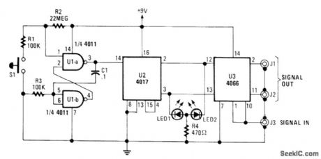
The A/B Switch circuit consists of three ICs and a handful of resistors. Two gates from a 4011 quad 2-input NAND gate (U1A and U1B) are configured as a monostable multivibrator that, when switch S1 is pressed, triggers a 4017 decade counter/divider, which has been set to recycle after a count of two. The outputs of U2 at pins 2 and 3 are fed to the control inputs of U3 (a 4066 quad bilateral syritch) at pins 12 and 13. Depending on which control input is high, either the J1 or J2 output is selected.With a little modification, the switch could be set to trigger at a set rate (automatically). With the addition of another 4066, it could have as many as 8 channels. One possible application would be in a security surveillance system. (View)
View full Circuit Diagram | Comments | Reading(2086)
TIME_ON_TOUCH_SWITCH
Published:2009/7/11 1:23:00 Author:May
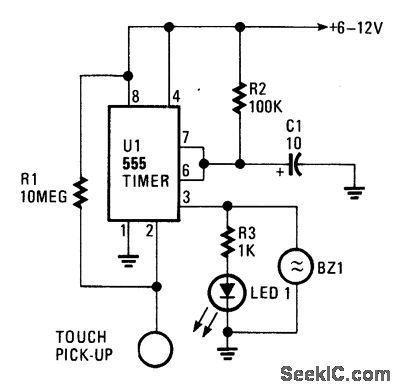
The circuit is built around a 555 oscillator (U1), which is tumed on when a trigger is applied by touching the touch terminal to pin 2 of U1. When activated, LED1 and BZ1 (a piezoelectric buzzer) tum on for the time period set by the values of R2 and C1. The ON-time of the touch circuit can be altered by changing the values of Q and R2.This touch switch can be powered from batter-ies so that it need not be near a 60-Hz power source for triggering. The extremely small amount of current supplied to the trigger input through the 10-MΩ resistor. R1, makes the input circuitry very sensitive to any external loading, and it is easily triggered by touching the pickup. (View)
View full Circuit Diagram | Comments | Reading(906)
TOUCH_SWITCH_Ⅱ
Published:2009/7/11 1:21:00 Author:May
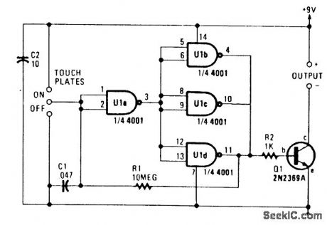
U1A and U1B/U1C/U1D form a bistable multivibrator that drives Q1, which switches the load. Touching the two upper contacts makes Q1 conduct; the two lower contacts cause Q1 to cut off. (View)
View full Circuit Diagram | Comments | Reading(710)
| Pages:5/15 123456789101112131415 |
Circuit Categories
power supply circuit
Amplifier Circuit
Basic Circuit
LED and Light Circuit
Sensor Circuit
Signal Processing
Electrical Equipment Circuit
Control Circuit
Remote Control Circuit
A/D-D/A Converter Circuit
Audio Circuit
Measuring and Test Circuit
Communication Circuit
Computer-Related Circuit
555 Circuit
Automotive Circuit
Repairing Circuit