
Circuit Diagram
Index 1100
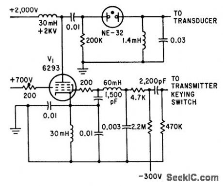
WATER_DEPTH_TELEMETER
Published:2009/7/23 22:26:00 Author:Jessie
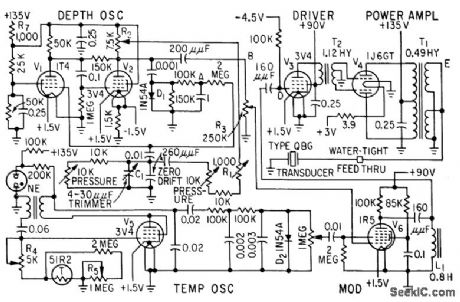
Determines exact depth of trawl net under water, for interception of desired school of fish. Continuous depth information is transmitted to trawler by modulated 21-kc ultrasonic beam, along with water temperature.-F. H. Stephens, Jr., Underwater Telemeter for Trawl Fishing, Electronics, 32:13, p 66-68. (View)
View full Circuit Diagram | Comments | Reading(874)
LOW_BATTERY_INDICATOR
Published:2009/7/3 4:23:00 Author:May
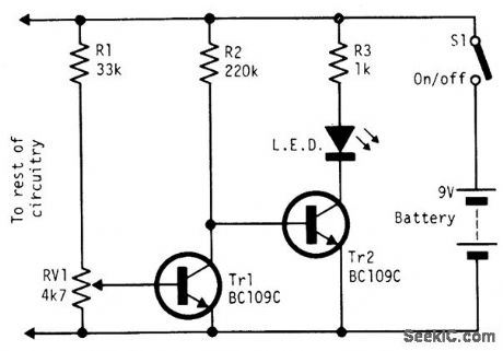
Under good battery conditions the LED is off. As the battery voltage falls, the LED begins to flash until, in the low battery condition, the LED lights continuously. Designed, for a 9-volt battery, with the values shown the LED flashes from 7.5 to 6.5 volts. (View)
View full Circuit Diagram | Comments | Reading(0)
20_100000_CPS_TRIANGULAR_WAVE_GENERATOR
Published:2009/7/23 22:26:00 Author:Jessie
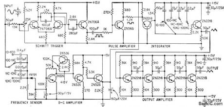
Sinusoidal frequency changes are con verted into proportional d-c volthage and fed into pulse amplifier and integrator to generate constant-amplitude triangular waveform for measuring dynamic linearity of amplifier as function of frequency. Schmitt trigger con verts input sine wave to constant-amplitude square wave. Frequency sensor produces d-c voltage proportional to frequency to serve as d-c source for pulse amplifier and integrator.-D. E. Cottrell, Frequency Sensor Stabilizes Triangular-Wave Generator, Electronics, 37:9, p 38-40. (View)
View full Circuit Diagram | Comments | Reading(838)
Instrumentation_amplifier_with_±_10_V_common_mode_range
Published:2009/7/23 22:26:00 Author:Jessie
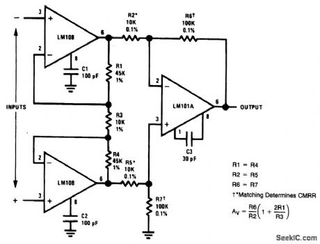
Compare this circuit to that of Fig,10-38. (View)
View full Circuit Diagram | Comments | Reading(714)
PROGRAMMING_OF_PROM
Published:2009/7/3 4:22:00 Author:May
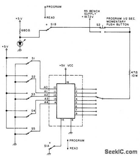
Simple circuit is effective for 82S23, DM8577, and 74188 PROMs.With DM8577, circuit changes logic 1s to 0s.With 82S23, 0s are changed to 1s. Set address switches for word to be programmed, set S1 to program position, set S3 to bit to be programmed, and push S2 momentarily (less than 0.5 s). To verify that bit has been programmed, return S1 to read position and observe LED.Supply can be three 6-V lantern batteries in series.-Ham Help, 73Magazine, April 1977, p 42. (View)
View full Circuit Diagram | Comments | Reading(2935)
TUNNEL_DIODE_TRANSCEIVER
Published:2009/7/23 22:49:00 Author:Jessie
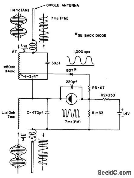
Is tuned for 114.Mc am signal and 7.Mc f-m output signal. 1N3714 tunnel diode acts as 7-Mc r-f oscillator and frequency modulator, while BD-7 back diode is 114-Mc detector.- Transister Manual, Seventh Edition, General Electric Co., 1964, p 361. (View)
View full Circuit Diagram | Comments | Reading(718)
LINEAR_SAWTOOTH_WITH_SPLIT_TIMING_CAPACITOR
Published:2009/7/23 22:49:00 Author:Jessie
To compensate for linearity deterioration, timing capacitor of emitter-coupled mvbr is split info two equal parts, and feed, back resistor is connected between center point and emitter of constant-current generator Q3.-B. Rakovic, One More Transistor Makes c linear Sawtooth, Electronics, 35:49, p 50-51. (View)
View full Circuit Diagram | Comments | Reading(681)
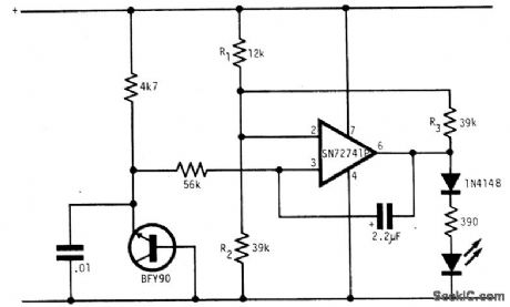
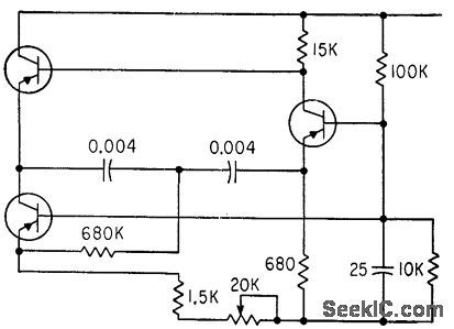
Function_generator
Published:2009/7/23 22:48:00 Author:Jessie
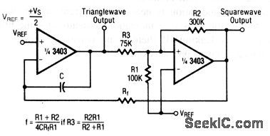
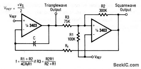
This circuit uses two sections of a 3403 op amp. The frequency of the triangle- and square-wave output is set by the values of R1, R2, C, and Rf, as shown. Raytheon Linear Integrated Circuits 1989, p. 4-159 (View)
View full Circuit Diagram | Comments | Reading(0)
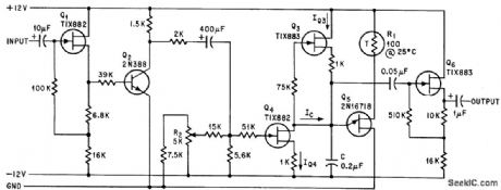
High_output_dual_tracking_regulator
Published:2009/7/23 22:48:00 Author:Jessie
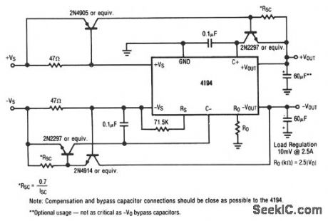
This circuit provides balanced output voltage with a load regulation of 10mV at .5A. (View)
View full Circuit Diagram | Comments | Reading(937)
22_KC_SONAR_1
Published:2009/7/23 22:48:00 Author:Jessie
key pulse allows Clapp oscillator to operate for 1 millisec at 22 kc, with keying 25 times per second.-L. H. Dulberger, Sonar to Survey Arctic Ocean Shelf Transmits Through Ice and Water, Electronics, 34:31, p 44-45. (View)
View full Circuit Diagram | Comments | Reading(851)
ULTRALINEAR_RAMP_GENERATOR
Published:2009/7/23 22:48:00 Author:Jessie
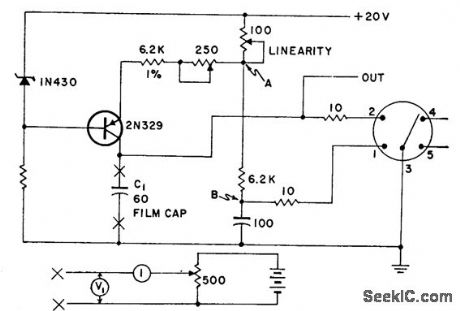
Used in high-accuracy low-speed voltage to pulse width converter. Linearity is better than 0.02% between 10 and 90% points of ramp. Test circuit below is substituted for C1 when adjusting linearity control.-Ultra linear Ramp Generator, Electronic Circuit Design Hand-book, Mactier Pub. Corp., N.Y., 1965, p 166. (View)
View full Circuit Diagram | Comments | Reading(1070)
150__to_300_MHz_frequency_doubler_1
Published:2009/7/23 22:48:00 Author:Jessie
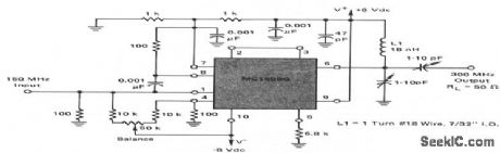
This circuit shows an MC1596 operating as a 150- to 300-MHz frequency doubler with suitable output filtering. All spurious outputs are 20 dB (or more) below the desired 300-MHz output. (View)
View full Circuit Diagram | Comments | Reading(749)
LINEAR_RAMP
Published:2009/7/23 22:48:00 Author:Jessie
Output voltage varies linearly with frequency within 98%, while peak voltage is constant of 0.6 v. Thermistor R1 provides temperature stability and source follower Q6 reduces loading.-D. D. Brooks and C. F. Johnson, Sawtooth Generator Uses FET as Constant Current Source, Electronics, 38:18, p 87. (View)
View full Circuit Diagram | Comments | Reading(1886)
2500_V_isolated_5_driver_5_receiver_RS_232_transceiver
Published:2009/7/23 22:48:00 Author:Jessie
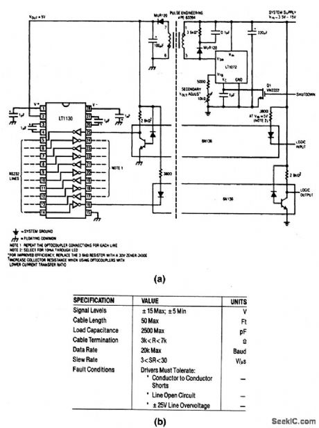
This circuit provides 2500-V isolation with optically coupled data lines, and an isolated 5-V supply. A powered transceiver eliminates the need for three supplies on both sides of the isolation transformer. The circuit meets the key RS-232 transceiver specifications (EIA RS232C.V28) shown in Fig. 6-68B. (View)
View full Circuit Diagram | Comments | Reading(656)
920_CHANNEL_CRYSTAL_REFERENCE
Published:2009/7/23 22:47:00 Author:Jessie
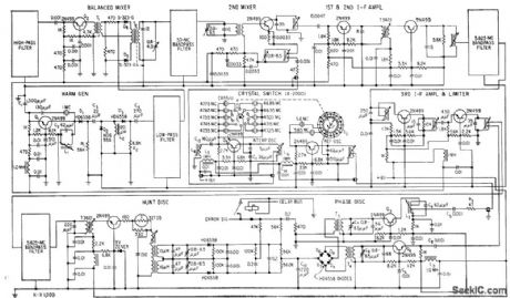
Controlled4equency mobile radio transceiver, operating in two bands, uses improved band. pass filter techniques that double number of channels per megacycle of spectrum, Oscillator-stabilized system is designed for 50-kc channel spacing and selects any of 920 channels between 30 and 76 Mc.-F. Brauer and D. Kammer, Mobile Radio System Provides 920 Channels, Electronics, 31:41, p 96-99. (View)
View full Circuit Diagram | Comments | Reading(684)
TRIANGULAR_WAVEFORM_GENERATOR
Published:2009/7/23 22:47:00 Author:Jessie
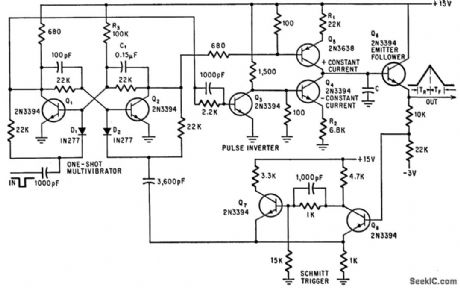
Used in synthesizing waveforms of predetermined shape. Produces single triangular pulse each time it is triggered externally. Output pulse has constant peak amplitude with no flattening, and independently adjustable rise time (R1) and all time (R2). Schmitt trigger Q7-Q8 resets one-shot mvbr Q1-Q2 and limits amplitude of output.-R. G. Teeter, Triangle Waveform Generator Resets Automatically, Electronics, 39:14, p 78. (View)
View full Circuit Diagram | Comments | Reading(983)
ENCODER_OUTPUT
Published:2009/7/23 22:44:00 Author:Jessie
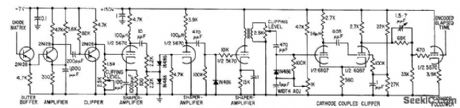
Output circuits are given for encoder used in storing and reading out elapsed time between consecutive randomly occurring events. Cathode follower stage provides low output impedance to give desired output waveform on crt for showing encoded elapsed time.-R. J. Kelso and J. C. Groce, Encoder Measures Random Event Time Intervals, Electronics, 32:12, p 48-51. (View)
View full Circuit Diagram | Comments | Reading(657)
HIGH_CURRENT_SCS_INTERVAL_TIMER
Published:2009/7/23 22:31:00 Author:Jessie
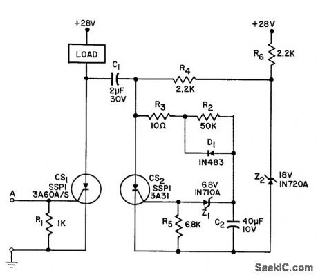
When triggered by low-level 5-microsec pulse, furnishes 1 amp to load for 1 sec. Advantages are simplicity and high reliability through use of silicon controlled switches.-Y. J. Lubkin, High Output Interval Timer, EEE, 10:9, p 92. (View)
View full Circuit Diagram | Comments | Reading(689)
High_power_step_up_voltage_regulator
Published:2009/7/23 22:31:00 Author:Jessie
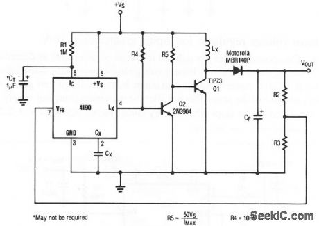
Figure 4-4 shows a step-up regulator for loads up to values are tailored to circuit requirements, as described for Fig. 4-2, except for R4 And R5, as shown. (View)
View full Circuit Diagram | Comments | Reading(971)
BOOSTING_SAWTOOTH_FREQUENCY
Published:2009/7/23 22:30:00 Author:Jessie
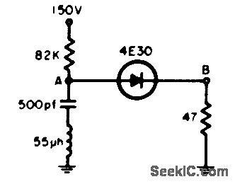
Inductor causes ringing and thereby extends operating frequency of sawtooth oscillator using four-layer diode. Will operate well above 100 kc.-P. Emile, Jr., Inductor Raises Useful Sawtooth Frequency, EEE, 12:7, p 28. (View)
View full Circuit Diagram | Comments | Reading(638)
| Pages:1100/2234 At 2010811082108310841085108610871088108910901091109210931094109510961097109810991100Under 20 |
Circuit Categories
power supply circuit
Amplifier Circuit
Basic Circuit
LED and Light Circuit
Sensor Circuit
Signal Processing
Electrical Equipment Circuit
Control Circuit
Remote Control Circuit
A/D-D/A Converter Circuit
Audio Circuit
Measuring and Test Circuit
Communication Circuit
Computer-Related Circuit
555 Circuit
Automotive Circuit
Repairing Circuit