
Circuit Diagram
Index 131
Series-Wound Direction And Speed Motor Control
Published:2013/3/29 4:29:00 Author:Ecco | Keyword: Series-Wound Direction , Speed Motor Control
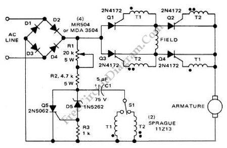
This is a motor controller circuit that control the speed and direction of series-wound Motors. This circuit employs silicon controlled rectifiers (SCR) Q1-Q4, that are triggered in diagonal pairs. The switch St is used to control which pair is turned on because either coupling transformer T2 or coupling transformer T1 is connected to a pulsing circuit by this switch. Here is the schematic diagram of the circuit:
(View)
View full Circuit Diagram | Comments | Reading(1036)
1 KW Power (Watt) Meter circuit
Published:2013/3/29 4:28:00 Author:Ecco | Keyword: 1 KW , Power (Watt) Meter
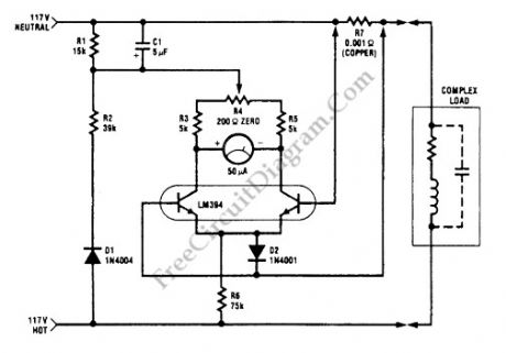
This watt-meter circuit has measurement range up to 1-KW. This circuit can give the complete (X)(Y) function although uses only one transistor. Actually, this circuit is used for 117 Vac±50 Vac operation. For lower or lower voltage, this circuit can be modified easily. This circuit only measure power on negative cycles. The advantages of this circuit is this circuit does not need external power supply. This circuit measures true power that is delivered to the load. Here is the schematic diagram of the circuit:
(View)
View full Circuit Diagram | Comments | Reading(1999)
Audio Power Amplifier circuit for AM Radio
Published:2013/3/29 4:27:00 Author:Ecco | Keyword: Audio Power Amplifier, AM Radio
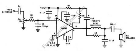
This is an AM radio power amplifier circuit. What is different with other general amplifier is that this circuit has a low-pass filter (passive type), built using R1C1 to limit the input-output frequency response. Additionally, a ferroxcube K5-001-001/3B with 3 turns of wire is used as ferrite bead at output filter. All components should be spaced very close to the IC. The ground and speaker lead must be twisted tightly. The supply lead and supply ground also must be twisted very tightly. Here is the schematic diagram of the circuit:
(View)
View full Circuit Diagram | Comments | Reading(2465)
Direct High Voltage DC Regulator circuit
Published:2013/3/29 4:26:00 Author:Ecco | Keyword: Direct, High Voltage, DC Regulator
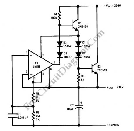
This regulator circuit stabilize the output voltage at 200V directly (without a transformer). Although the output voltage is high, this circuit only suffer a tension of the voltage drop (Vinput-Voutput), which is suffered mainly by the transistors. The op-amp suffers even less tension, since it regulate the applied voltage at their pins around the level of transistor’s bias voltage level.
(View)
View full Circuit Diagram | Comments | Reading(1959)
Capacitor ESR Meter circuit
Published:2013/3/29 4:25:00 Author:Ecco | Keyword: Capacitor ESR Meter
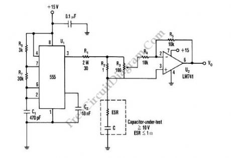
This is schematic diagram of capacitor ESR meter circuit. ESR is equivalent series resistance, and this parameter is used to express the resistance value of any electronic component that basically is not a resistor. ESR is present on many non-resistor component, such as capacitor, inductor, or semiconductor. The circuit shown in this schematic diagram is used to measure equivalent series resistance (ESR) of a capacitor. This ESR meter circuit uses 555 IC as 50-kHz square-wave generator. The ±180mA current waveform is driven in the capacitor-under-test by U1, through R2 and R1. Adjust R3 to the proper value, the inverting amplifier (U2) will null the voltage drop across the equivalent series resistor. The minimum voltage that can be produced at VO the pure capacitor voltage. Here is the schematic diagram of the circuit:
(View)
View full Circuit Diagram | Comments | Reading(9309)
Funk (Twang) Guitar Effect Box circuit
Published:2013/3/29 4:25:00 Author:Ecco | Keyword: Funk (Twang) Guitar Effect Box
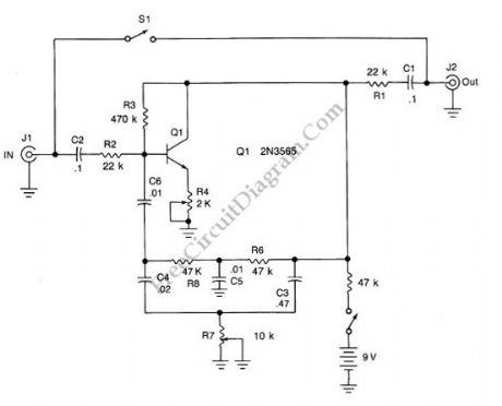
This is an audio effect circuit that give extra oscillation to your guitar, percussive, or semi percussive instruments, you can call it a funk box. This guitar effect circuit is basically a damped oscillator that is set slightly below its critical oscillation point. The oscillator part is constructed by feeding back the output signal through a bandpass circuit, with the center frequency is adjusted by potentiometer R7 to add an extra “twang” , adjustable from low to high pitched timbre. Potentiometer R4 is used to adjust the gain of the oscillator, should be set to damp the oscillation at the desired decay time. To adjust it, turn the knob slowly until a steady oscillation occurs, and turn back slightly just before it happens (the oscillation should ceases slowly). Here is the schematic diagram of the circuit:
(View)
View full Circuit Diagram | Comments | Reading(1541)
Versatile Discrete Monostable Multivibrator
Published:2013/3/28 4:15:00 Author:Ecco | Keyword: Versatile Discrete, Monostable Multivibrator
This is a versatile discrete monostable circuit. This circuit consist of 2N3819 JFET and 2N3704 transistors. This monostable multivibrator circuit has additional input to enable or inhibit the function at any time without causing output pulse. The input of this circuit accept a standard digital IC voltage levels. Here is the schematic diagram of the circuit:
(View)
View full Circuit Diagram | Comments | Reading(2335)
22W Amplifier circuit for 12V Power Supply Systems
Published:2013/3/28 4:14:00 Author:Ecco | Keyword: 22W Amplifier, 12V Power Supply
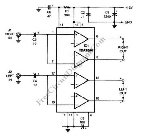
This is a 22-W Amplifier circuit that is designed for or 12-V DC power supply Systems. There are many application for this circuit, such as in car audio application. In car electrical power supply system, the 12V power supply will be provided by the host vehicle’s battery. The capacitor C3 is used to give ripple rejection, since noisy power supply voltage is common in automotive electrical system. The power supply noise signal on car power supply is decoupled by the capacitors C2 and C1. Smaller capacitor C2 is needed to decouple the high frequency noise, since the larger cap (C1) usually has high equivalent series inductance that prevent the high frequency noise (such as glitch or spike) to be bypassed. The capacitors C5 couple the incoming audio signal to IC1 while decoupling static DC offset. For better bass response, this circuit prevent rolling off of the low audio frequencies by choosing a relatively large capacitance for small signal, 10μF capacitors. Here is the schematic diagram of the circuit:
(View)
View full Circuit Diagram | Comments | Reading(1957)
Sferic Signal Simulator circuit
Published:2013/3/28 4:13:00 Author:Ecco | Keyword: Sferic Signal Simulator

Sferic signal simulator is used to produce an impulse signal which simulates the waveform of a sferic, a radio atmospheric signals produced by a lightning strike. In time domain, the waveform of a sferic signal is a single high amplitude spike. When this pulse is analyzed in frequency domain, it will show a wide band spectrum ranging from few kilohertz to several tens of kilohertz. Here is the schematic diagram of the sferic signal simulator circuit:
(View)
View full Circuit Diagram | Comments | Reading(990)
Optical Theremin
Published:2013/3/28 4:13:00 Author:Ecco | Keyword: Optical Theremin
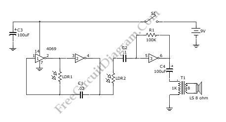
Normally, Theremin works by detecting hand proximity using capacitive coupling method. A Theremin circuit shown in the schematic diagram below use different method to control the pitch. The oscillator of this tone generator, both the volume and frequency are controlled using LDRs, a light sensitive electronic component, so we can call this circuit an optical Theremin. Look at the following schematic diagram:
(View)
View full Circuit Diagram | Comments | Reading(2657)
Logic Power Control circuit diagram for 78xx Regulator
Published:2013/3/28 4:12:00 Author:Ecco | Keyword: Logic Power Control , 78xx Regulator
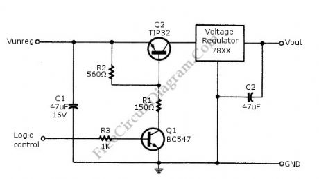
Logic power control of analog regulator can be useful in application where a digital circuit/controller need to control power source, such as in EEPROM programmer or other power controls. This is a circuit provide ON-OFF control for 78xx regulator using digital (TTL or CMOS) signal level. This circuit uses transistors in series with the 78XX regulator, which it’s base is controlled by logic level input. Here is the schematic diagram of the circuit:
(View)
View full Circuit Diagram | Comments | Reading(2384)
Tachometer Circuit Diagram with Single Transistor
Published:2013/3/28 4:10:00 Author:Ecco | Keyword: Tachometer , Single Transistor
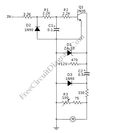
A schematic diagram of simple tachometer circuit is shown below. Using only a single transistor as the active component, this tachometer would probably be the simplest one. The input of this circuit can be picked up from ignition pickup coil, or other wiring that gives ignition wave-form. This tachometer circuit works for 0 to 6,000 rpm. R3 is used for calibrating the full scale meter reading, to get valid rpm. The zener diode D1 is used to stabilize the 12-V supply. Here is the schematic diagram of the circuit:
(View)
View full Circuit Diagram | Comments | Reading(1470)
Pre-Amplifier Circuit Diagram for Oscilloscope
Published:2013/3/28 4:09:00 Author:Ecco | Keyword: Pre-Amplifier, Oscilloscope
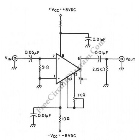
An oscilloscope amplifier with 20 dB voltage gain is provided by this circuit with a frequency range from 0.5 to 50 MHz. By increasing the value of the 0.05 uF capacitor or try removing the capacitor, we can extend the low frequency response of this circuit. A particularly small level of input noise is delivered by this circuit, measured at approximately 20uA over a bandwidth range at 15 MHz. By adjusting the gain potentiometer connected between pins 3 and 10, then adjust the 1-KΩ trimmer potentiometer for an exact voltage gain of 10 are the ways to calibrate the gain. This helps preserve the scale factor of the oscilloscope.
(View)
View full Circuit Diagram | Comments | Reading(2112)
Fast Amplifier Circuit diagram with DC Stabilization
Published:2013/3/28 4:09:00 Author:Ecco | Keyword: Fast Amplifier , DC Stabilization
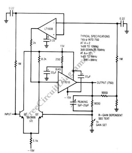
This amplifier circuit combines the LT1010 and a fast discrete stage with an LT1008 based dc stabilizing loop. A differential stage which is single-ends into the LT1010 is formed by Q1 and Q2. An output of 1 V pk-pk into a typical 75-Ω video load is delivered by the circuit. With gain = 2, the gain is considered flat up to 10MHz since it only attenuated about -0.5dB, with the -3 dB point occurring at 16 MHz. At gain = 10, this amplifier flat curve will be up to 4 MHz (0.5dB deviation), with -3 dB point at 8 MHz. The peaking adjustment should be optimized under loaded output conditions. This is a simple stage amplifier for fast applications where relatively low output swing is required. For video amplifier application, 1 V pk-pk output works nicely. A possible problem is the relatively high bias current, typically 10 μA. Additional swing is possible, but more circuitry is needed.
(View)
View full Circuit Diagram | Comments | Reading(1285)
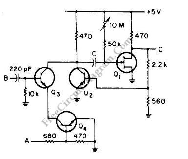
One Direction Motion Sensor circuit
Published:2013/3/28 4:08:00 Author:Ecco | Keyword: One Direction Motion , Sensor
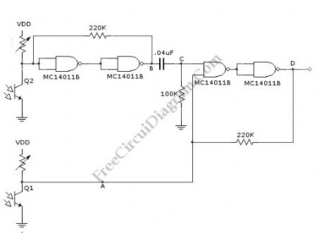
This is a one direction motion sensor circuit. This motion sensor circuit is used to detects an object passing in one direction, ignoring an object that going to opposite way. This circuit uses two sensors to identify the movement only in one direction. The basic principle of this circuit is simple, where one sensor is used to generate a short pulse, and the other sensor is used to block of turn of the gate. The phototransitors give high output on their collectors when there is an object blocking the light. By a 0.4uF differentiator capacitor, the interruption of light at Q2 sensor will produce short pulse at point C. But this short pulse will only appear at the output if a high signal appears at A. This condition will be satisfied if the light to Q1 is blocked by the object when the object is passing through Q2, means that the direction should be from Q1 to Q2. Here is the schematic diagram of the circuit:
(View)
View full Circuit Diagram | Comments | Reading(2056)
True Stereo Indicator Detecting L-R Signal Difference circuit
Published:2013/3/28 4:07:00 Author:Ecco | Keyword: True Stereo Indicator, L-R Signal Difference
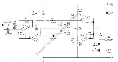
This true stereo indicator is different from what we usually find on FM radio receiver, which is usually a pilot tone detector. A stereo broadcast from FM radio station contain pilot tone, but a presence of pilot tone doesn’t necessarily a stereo broadcast signal since a mono FM transmitter ca broadcast pilot tone as well. Since this circuit detect the difference between left and right channel, this circuit can detect a real stereophonic programs. When there is no difference between R and L input signals, the output A1 and output A2 is at the same potential. That will make a a virtual ground rail at half the supply voltage. Here is the schematic diagram of the circuit:
(View)
View full Circuit Diagram | Comments | Reading(1442)
Discrete Sliding Tone (Frequency Ramp) Doorbell circuit
Published:2013/3/28 4:06:00 Author:Ecco | Keyword: Discrete Sliding Tone , Doorbell
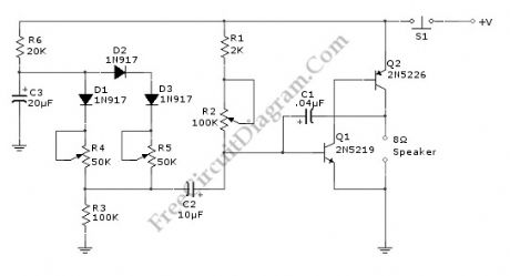
This doorbell circuit produces a low tone that will slide up to higher frequency. The equivalent total resistance connected between the base of Q1 and ground (Rbg) , and coupling capacitor C1 determines the AF oscillator’s frequency. The resistance (Rbg) is equal to (R2+R1)R3. Here is the schematic diagram of the circuit:
(View)
View full Circuit Diagram | Comments | Reading(2803)
Direct Coupled Discrete Astable Multivibrator circuit
Published:2013/3/28 4:04:00 Author:Ecco | Keyword: Direct Coupled Discrete, Astable Multivibrator
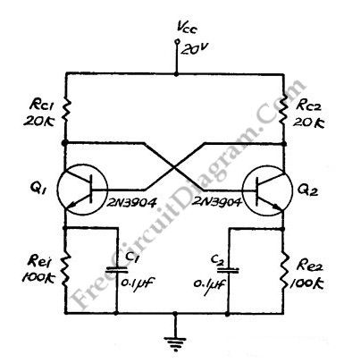
This flip-flop circuit is a free running/astable multivibrator one, with bases and collector of both emitter biased transistor are directly coupled to each other. Switching action is supported by means of capacitor in each emitter circuit. This configuration produce a triangle waves at emitters. Since neither transistor can remain permanently cut off, then a free running oscillation will be generated. We can use single 0.1 uF capacitor between emitters in place of C1 and C2.
(View)
View full Circuit Diagram | Comments | Reading(2240)
AD532 Multiplier IC diagram and Its Pin Configurations
Published:2013/3/28 4:04:00 Author:Ecco | Keyword: Multiplier IC
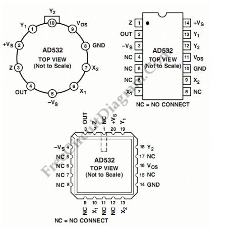
The AD532 is the first pre-trimmed single chip monolithic multiplier/divider. This device guarantees a maximum multiplying error of +- 1% and a +-10 V output voltage without the need for any output op amp or external trimming resistors. It’s simplicity of use provides design engineers with an attractive alternative to modular multipliers because the AD532 is internally trimmed. The AD532 is monolithic construction provides significant advantages in size, reliability and economy. The AD532 also can be used as a direct replacement for other IC multipliers that require external trim network. This device can be applied on various application such as power measurement, multiplication, division, squaring, square rooting, algebraic computation and instrumentation applications. The AD532 also available in chip form.
(View)
View full Circuit Diagram | Comments | Reading(1063)
Single Chip Circuit diagram for Multiplication Operation
Published:2013/3/28 4:03:00 Author:Ecco | Keyword: Single Chip , Multiplication Operation
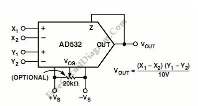
The AD532 should be connected as the following figure for operation as a multiplier. We can fed the input differentially to the X and Y inputs, or single ended by simply grounding the unused input. Connect the inputs according to the desired polarity in the output. To close the feedback loop around the op amp, the Z terminal is tied to the output. The offset adjust Vos is optional and is adjusted when both inputs are zero volts to obtain zero out, or to buck out other system offsets.
(View)
View full Circuit Diagram | Comments | Reading(694)
| Pages:131/2234 At 20121122123124125126127128129130131132133134135136137138139140Under 20 |
Circuit Categories
power supply circuit
Amplifier Circuit
Basic Circuit
LED and Light Circuit
Sensor Circuit
Signal Processing
Electrical Equipment Circuit
Control Circuit
Remote Control Circuit
A/D-D/A Converter Circuit
Audio Circuit
Measuring and Test Circuit
Communication Circuit
Computer-Related Circuit
555 Circuit
Automotive Circuit
Repairing Circuit