
Circuit Diagram
Index 133
Micro- pending power square wave generating circuit
Published:2013/3/28 1:58:00 Author:Ecco | Keyword: Micro- pending power, square wave, generating
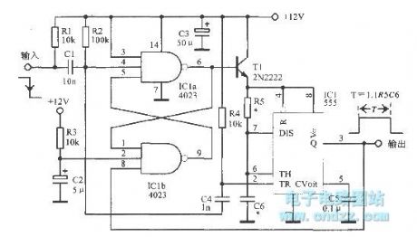
Micro- pending power square wave generating circuit is shown as figure.
(View)
View full Circuit Diagram | Comments | Reading(951)
100Hz Wien bridge
Published:2013/3/28 2:00:00 Author:Ecco | Keyword: 100Hz Wien bridge
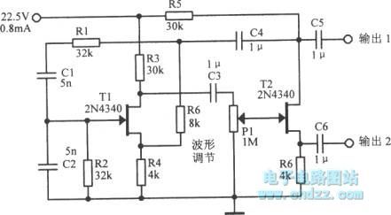
100Hz Wien bridge is shown as figure.
(View)
View full Circuit Diagram | Comments | Reading(768)
The square wave oscillator with 2ns 1:1 edge
Published:2013/3/28 1:51:00 Author:Ecco | Keyword: square wave oscillator , 2ns 1:1 edge
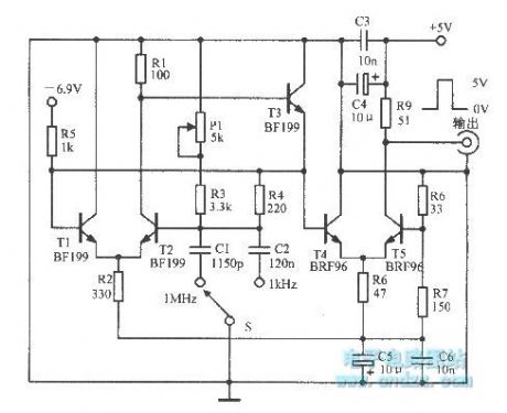
The square wave oscillator with 2ns 1:1 edge is shown as figure.
(View)
View full Circuit Diagram | Comments | Reading(1270)
The voltage - controlled oscillator with flip - flop
Published:2013/3/28 1:52:00 Author:Ecco | Keyword: voltage - controlled oscillator , flip - flop
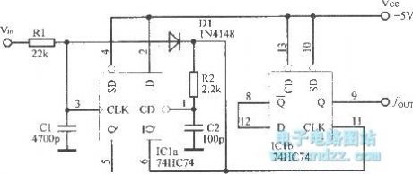
The voltage - controlled oscillator with flip - flop is shown as figure.
(View)
View full Circuit Diagram | Comments | Reading(1562)
The precise second pulse signal generator
Published:2013/3/28 2:01:00 Author:Ecco | Keyword: Precise , second , pulse signal generator
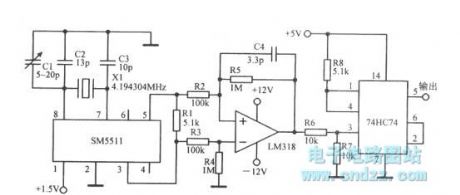
Precise second pulse signal generator is shown as figure.
(View)
View full Circuit Diagram | Comments | Reading(989)
The three-phase bridge rectifier pop n-type filter circuit
Published:2013/3/28 1:47:00 Author:Ecco | Keyword: three-phase, bridge rectifier , pop n-type filter
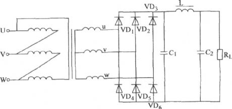
The three-phase bridge rectifier pop n-type filter circuit is shown as figure.
(View)
View full Circuit Diagram | Comments | Reading(1017)
PCB Drill Speed Controller with 555
Published:2013/3/27 4:24:00 Author:Ecco | Keyword: PCB Drill Speed, Controller
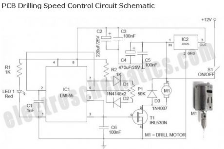
Described here is a simple, inexpensive and useful circuit for electronics hobbyists. The circuit is nothing but a PCB drill speed controller, which can be used to control the speed of any 12VDC small pcb drilling units. Such portable units are now widely available, and even a hobbyist can make it without too much difficulty.
(View)
View full Circuit Diagram | Comments | Reading(1843)
Industrial Battery Charger Project Kit
Published:2013/3/27 4:23:00 Author:Ecco | Keyword: Industrial, Battery Charger, Project Kit
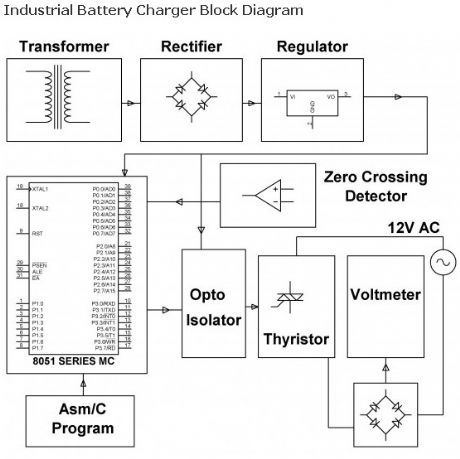
The assignment is intended for charging battery(s) by DC from AC supply of power. DC power supplied for a battery’s charger is a derivative from a thyristor controlled rectifier mechanism. AC supply of power is useful to a link rectifier consisting of diodes and a TRIAC achieving preferred power from the micro controller.
(View)
View full Circuit Diagram | Comments | Reading(1789)
Run/Stop Relay Circuit
Published:2013/3/27 4:22:00 Author:Ecco | Keyword: Run/Stop Relay
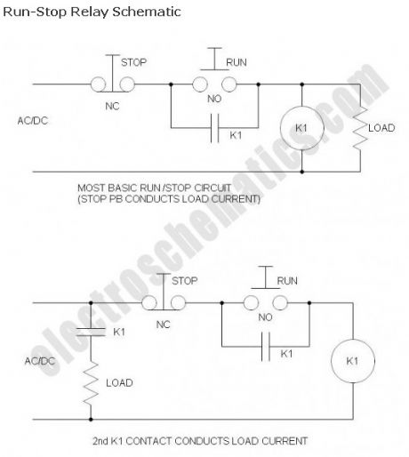
Safety is a major concern in a good many motor-driven applications. This is true in industrial applications where motion starts when power is applied and especially true when power is restored after an outage. In such cases, unwanted or unexpected motion is a risk to life or limb. The most simple solution to this problem is the simple, time-proven Run /Stop Relay Circuit.
With this control circuit, motion cannot commence (or restart) without the operator’s specific pushbutton command. While simple, there are numerous variations and enhancements as you will see, and the benefits are clearly obvious.
(View)
View full Circuit Diagram | Comments | Reading(1143)
Momentary Switch with 555
Published:2013/3/27 4:20:00 Author:Ecco | Keyword: Momentary Switch , 555
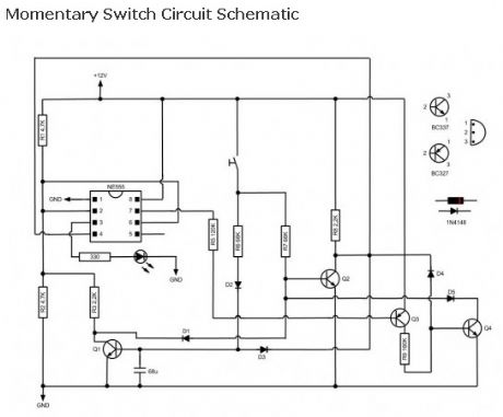
Based on NE555 this circuit turns on and off the IC output by a momentary switch. In other words it works as a mechanical latching relay, but the circuit backs to the start condition when you switch off the power supply. This feature is often required in automotive devices. No relay contacts are used, infact I connected the output to a led.
(View)
View full Circuit Diagram | Comments | Reading(1713)
Arduino Panic Alarm
Published:2013/3/27 4:16:00 Author:Ecco | Keyword: Arduino Panic Alarm
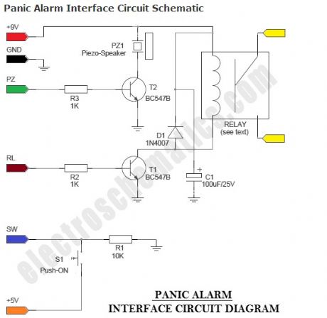
Panic Alarm circuit consists of two equally important parts. The first part is the ready-made Arduino Microcontroller board, and the second part is an interface circuit which can be wired on a piece of prototyping board. You can use any standard 9V battery to power the whole circuit, and the Push-ON (push ‘n’ hold) switch (S1) to activate the alarm function. An additional Electro-Magnetic Relay (EMR) is also attached to the interface circuit.
(View)
View full Circuit Diagram | Comments | Reading(1413)
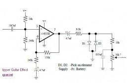
Axe Grinder Electric Guitar Effect
Published:2013/3/27 3:58:00 Author:Ecco | Keyword: Axe Grinder , Electric Guitar Effect
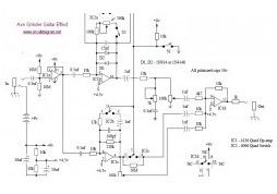
Here the schematic diagram of Axe Grinder Electric Guitar Effect. You may download the PDF version at the end of the post. The Axe Grinder is designed with a few key fetures in mind, it not only serves a wide range of distortion sounds clipping part of the effect, it also gives the user the ability to overload their amp with a greatly boosted clean tone.
(View)
View full Circuit Diagram | Comments | Reading(1156)
Dynamic Mic Compressor
Published:2013/3/27 3:57:00 Author:Ecco | Keyword: Dynamic Mic Compressor
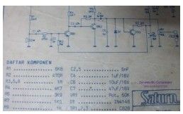
The circuit below is a Dynamic Mic Compressor circuit is simple but the results are quite satisfactory. Audio output sounded outstanding. The principle of this circuit is very simple, the first transistor is used as Mic Pre-Amp. Then a second transistor used as a buffer. And the third transistor is a feedback circuit.
(View)
View full Circuit Diagram | Comments | Reading(1471)
Fender Bassman 5F6-A
Published:2013/3/27 3:57:00 Author:Ecco | Keyword: Fender Bassman
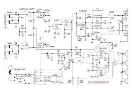
Here the schematic diagram of Fender Bassman 5F6-A amplifier. This circuit is a tube powered amplifier which is used as a bass guitar amplifier. Fender Bassman was a bass amplifier introduced by Fender in 1952. Although it was originally designed for bass guitars, it is often used for normal electric guitar in rock and roll, blues and country music.
(View)
View full Circuit Diagram | Comments | Reading(1426)
Dan Amstrong Blue Clipper Guitar Effect
Published:2013/3/27 3:56:00 Author:Ecco | Keyword: Dan Amstrong, Blue Clipper Guitar Effect
Below diagram is the circuit diagram of Dan Amstrong Blue Clipper effect for electric guitar: Download the above Blue Clipper guitar effect circuit in PDF file HERE The following PCB design is the another original Dan Amstrong Blue Clipper guitar effect circuit:
(View)
View full Circuit Diagram | Comments | Reading(1063)
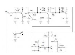
12V Stereo Tone Control
Published:2013/3/27 3:54:00 Author:Ecco | Keyword: 12V , Stereo Tone Control
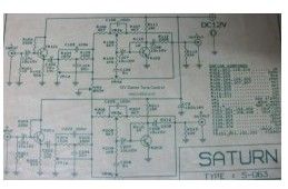
The following diagram is the circuit diagram of 12V stereo tone control which also available in kit, you may find the kit at electronic part store around your place. The circuit build based on ordinary tone control circuit, using 2 transistors FCS9014 in each channel, so there are will be 4 transistors in this 12v stereo tone control.
(View)
View full Circuit Diagram | Comments | Reading(1535)
Electro Harmonix Big Muff Pi Effect
Published:2013/3/27 3:53:00 Author:Ecco | Keyword: Electro Harmonix , Big Muff Pi Effect
The following diagram is the schematic diagram of electric guitar effect: Electro Harmonix (EH) Big Muff Pi. The EH Big Muff Pi would probably be better making the change by a modern input-jack power and a DPDT bypass switch. The types of transistors and diodes are unknown. It is likely that any high gain NPN transistor and diode 1N914 will work.
(View)
View full Circuit Diagram | Comments | Reading(890)
ACTOR : Active Tone Control
Published:2013/3/27 3:52:00 Author:Ecco | Keyword: ACTOR, Active Tone Control
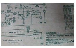
The following diagram is the schematic diagram of Active Tone Control circuit, or we often call thic circuit as “ACTOR” Active Tone Control or ACTOR is a electronic audio circuit that serves to increase the Loudness (Bass and Treble audio signal) is active because it uses the Baxandall system.
(View)
View full Circuit Diagram | Comments | Reading(1145)
BOSS Slow Gear SG-1
Published:2013/3/27 3:51:00 Author:Ecco | Keyword: BOSS Slow Gear
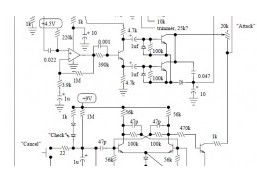
This is the circuit diagram of BOSS Slow Gear SG-1 effect for electric guitar. The Slow Gear SG-1 effect sounded like a guitar player riding the volume knob of the guitar. This produced a cool swelling sound with a gradual attack, almost like a violin.
(View)
View full Circuit Diagram | Comments | Reading(1918)
Tube Mic Pre-Amp
Published:2013/3/27 3:51:00 Author:Ecco | Keyword: Tube Mic Pre-Amp
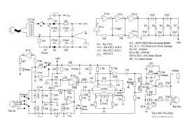
The following diagram is the circuit diagram of tube mic pre amplifier 12AX7. This circuit is little hard to built. You must have an intermediate or advanced skills to build this circuit. All capacitors with value of 33uF are 16V, while the all others are 50V unless marked otherwise. Resistors marked with “#” are 1% metalfilm resistor type.
(View)
View full Circuit Diagram | Comments | Reading(1845)
| Pages:133/2234 At 20121122123124125126127128129130131132133134135136137138139140Under 20 |
Circuit Categories
power supply circuit
Amplifier Circuit
Basic Circuit
LED and Light Circuit
Sensor Circuit
Signal Processing
Electrical Equipment Circuit
Control Circuit
Remote Control Circuit
A/D-D/A Converter Circuit
Audio Circuit
Measuring and Test Circuit
Communication Circuit
Computer-Related Circuit
555 Circuit
Automotive Circuit
Repairing Circuit