
Circuit Diagram
Index 140
DC Voltage Doubler Circuit +12V to +24V using LM2586
Published:2013/3/22 3:24:00 Author:Ecco | Keyword: DC Voltage Doubler, +12V to +24V
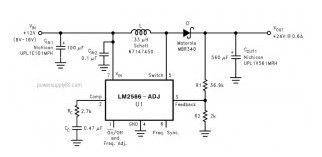
This is the DC voltage doubler circuit which build based National IC LM2586. The circuit will doubling the input voltage of 12VDC to become 24VDC. Heatsink is required for this circuit.
The LM2586 is a monolithic integrated circuits specifically designed for flyback, step-up (boost), and forward converter applications. The device is available in 4 different output voltage versions: 3.3V, 5.0V, 12V, and adjustable.
(View)
View full Circuit Diagram | Comments | Reading(2444)
Additional Power Supply for USB Devices
Published:2013/3/22 3:24:00 Author:Ecco | Keyword: Additional Power Supply , USB Devices
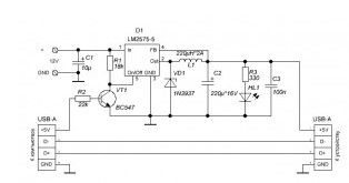
Much the use of USB devices today, sometimes cause lack of power problem. How to know the maximum current that can be obtained from a single USB connector is limited to 500 mA. If your device requires more current, then it must involve an additional one USB connector, which maybe not available. This problem can be solved by an additional instrument to use an external unregulated power and convert it to 5 Volt.
You can use two different approaches. You can use two different approaches. the first and perhaps easiest – is to use a simple linear regulator, but this raises other problems – wasteful spending power, but you can go the other way and use a pulse transformer, which is more economical.
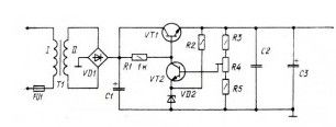
Note : The basis of the converter is a PWM controller based on integrated circuits LM 2575-5, having the output of 5 volts with a current up to 1A. To enable / disable the converter uses pin 5 On / Off , controlled transistor VT 1.
(View)
View full Circuit Diagram | Comments | Reading(1307)
Voltage Converter from 1.5V to 3V
Published:2013/3/22 3:19:00 Author:Ecco | Keyword: Voltage Converter , 1.5V to 3V
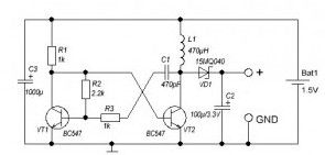
A simple scheme to generate the inverter voltage from 1.5V to 3V can be made on the basis of slightly modified the well-known multivibrator. Under these denominations in the scheme of the frequency converter is approximately 130 kHz. Inductance value can be calculated or chosen experimentally. But you can simply adjust the frequency of the converter to produce maximum output voltage. Schottky diode VD1 can be replaced by any other similar characteristics.
For further stabilization of the output voltage can be applied to the zener voltage of 3V – 3.3V. This scheme can be used to power a LED or low power devices based on the microcontroller, for example, MSP430.
(View)
View full Circuit Diagram | Comments | Reading(2213)
Mains AC / DC Converter with SR03x
Published:2013/3/22 3:14:00 Author:Ecco | Keyword: Mains AC / DC Converter
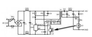
This is another Transformerless power supply. IC voltage regulators for SR03x made by Supertex is connect directly to main voltage and get the output voltage to 3.3V and 5V chip for SR036 SR037 to 30mA output current. To use this chip is not necessary to use step-down transformer or coil. Rectified input voltage to the diode bridge diodes D1 – D4 (figure point a) is input circuits IC1 SR03x.
(View)
View full Circuit Diagram | Comments | Reading(998)
Low Power Bipolar Stabilizer
Published:2013/3/22 3:13:00 Author:Ecco | Keyword: Low Power, Bipolar Stabilizer
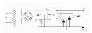
The stabilizer is made on the integrated circuit KR142EN6. IC is a bipolar voltage regulator with an output voltage of + / -15 V. Maximum load current is 200 mA. Enough to supply a pre-amplifier or the early stages of the power amplifier.Diode bridge – any of a series of KTS407, KTS405, KTS402.Transformer with two secondary windings, the voltage on each – 16 Volt.
(View)
View full Circuit Diagram | Comments | Reading(803)
6.8 Volt Transformerless Power Supply
Published:2013/3/22 3:13:00 Author:Ecco | Keyword: 6.8 Volt, Transformerless Power Supply

The scheme is designed for voltage and current of 6.8 V 300mA. The voltage can be changed by replacing the Zener D4 and, if necessary, D3. A setting on the radiators of transistors can be increased and the load current.Diode bridge – any, is nice and a reverse voltage of at least 400 volts. By the way, we can recall the ancient and diode D226B, once terribly popular.
(View)
View full Circuit Diagram | Comments | Reading(1353)
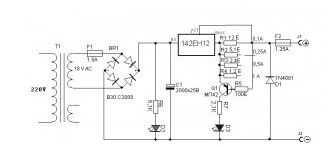
1.5V-25V Power Supply with Preregulator
Published:2013/3/22 3:12:00 Author:Ecco | Keyword: 1.5V-25V , Power Supply , Preregulator
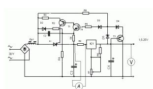
This circuit using KR142EN12 (analog – LM317 ) ic regulator that can handle load currents up to 2 amperes. For higher currents can be used IC LT1083/84/85 that each can handle currents 7/5/3A. 2000uF capacitor C3 is selected from the calculation of the current 1 Ampere. Resistor R9 is used as a current sensor to an ammeter.
In fact, not all of the thyristor passes the half-wave rectified voltage, and some of them, depending on the output voltage and load current. This can significantly reduce the power dissipated in the regulating element, especially at low output voltages and currents.
(View)
View full Circuit Diagram | Comments | Reading(1509)
70 W Switching Power supply with KA2S0880 IC
Published:2013/3/22 3:11:00 Author:Ecco | Keyword: 70 W, Switching Power supply
The schematic shows the power supply capacity of 70W stereo amplifier Power converter is built on a chip KA2S0880, which includes all the necessary components to build the primary of the power supply. This chip is very stable in operation and has all the necessary protections.
(View)
View full Circuit Diagram | Comments | Reading(1882)
60 Watt Laptop Battery Charger
Published:2013/3/22 3:02:00 Author:Ecco | Keyword: 60 Watt , Laptop Battery Charger
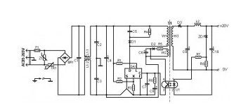
The circuit is designed for laptop battery charger with 20V output voltage. This circuit uses TOP 246 Y made by Power integrations. TOP 246 Y eliminates half the discrete components compared with the UC3842. As promised Power Integration, this IC is more reliable, has a smaller form, reducing the time in designing and saving costs.
(View)
View full Circuit Diagram | Comments | Reading(2417)
5 Volt/1.5A Switching Power Supply based TNY264P
Published:2013/3/22 3:01:00 Author:Ecco | Keyword: 5 Volt, 1.5A, Switching Power Supply
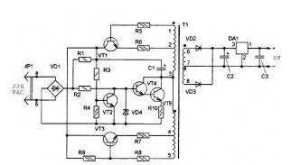
In recent years, this family of MC reached great popularity, they can be found on the DVD-player, modem, DSL, cost-supplying device, waiting for power supplies, etc. And in fact they went on the radio market very quickly.
In fact, the figure of the power supply has two additional outputs for 3 and 9V.But in this series only has 5 V output. This circuit can be used to add power to usb devices like external hard disks.
(View)
View full Circuit Diagram | Comments | Reading(1269)
Laser Dioda Power Supply
Published:2013/3/22 3:00:00 Author:Ecco | Keyword: Laser Dioda , Power Supply
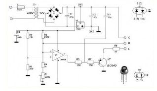
Diode laser has three pins and consists of (a diode that emits a laser beam), and control the photodiode, which is designed to control power output. Anode and cathode of the diode laser is connected to the control pin and also connected with the case.
The tracking scheme with a feedback current produces a forward bias diode laser. The stabilizer is automatically adjusted return current supervisory diode, in order to maintain the installed capacity of radiation. Adjusting the current is an operational amplifier OP, in the inverse input is fed a reference voltage of 2.5 V with a resistor R1, R2.
The potential for direct input 3 varies with the inverse photodiode current of the laser diode. Indeed, the photodiode current passes through resistors R4 and Aj, is converted into a voltage. The output voltage of OP depends on the photodiode reverse current, as well as the trimmer Aj, which is determined by the light beam
(View)
View full Circuit Diagram | Comments | Reading(1146)
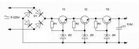
12V DC Voltage Doubler Circuit
Published:2013/3/22 2:59:00 Author:Ecco | Keyword: 12V, DC Voltage, Doubler
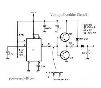
This is the circuit diagram of DC voltage doubler / DC converter. The circuit will convert 12VDC power supply to become a 24VDC at and 18VDC. Almost any PNP or NPN power transistors should be work for this circuit.
(View)
View full Circuit Diagram | Comments | Reading(3871)
Charger for All Battery Types
Published:2013/3/22 2:58:00 Author:Ecco | Keyword: Charger, All Battery Types
Note that the stability is observed when the load current and will change slightly of the supply voltage. Likewise, the fact is usually overlooked, but if you want a perfect stability – stabilize the power supply. Calculation of the current is very simple – the current in amperes is equal to 1.2 divided by the resistance R1 in Ohms. To display the current used transistor (germanium necessarily because of the low voltage opening) that allows you to visually observe the currents to 50 mA.
Diode D1 and F2 fuse protects the charger from the battery reverse. Capacitance C1 is selected from the formula: 1 amp should 2000uF.
The advantages of the proposed device: short-circuit protected it does not matter the number of elements in rechargeable battery and type – can be charged and sealed acid and lithium 12.6 3.6 and 7.2 V alkaline Switch current should be included exactly as shown on the chart – in order to remain in any manipulation of the resistor R1. The use of alternating low-impedance resistor is undesirable because of instability of sliding contact with load currents over 0.2 A.
(View)
View full Circuit Diagram | Comments | Reading(2156)
The Voltage Regulator With a Field Effect Transistor
Published:2013/3/22 2:46:00 Author:Ecco | Keyword: Voltage Regulator, Field Effect Transistor
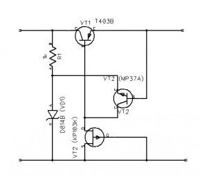
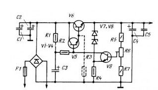
Feature of this transistor compensation voltage (see picture) – used in the feedback field effect transistor VT3, which acts as a dynamic load for the transistor VT2. Because of this factor increases the voltage regulation: when the input voltage from 11 to 19 V output voltage varies within ± 60 mV. Rated output voltage using Zener type D814B is 9 V.
Rated load stabilizer – 0.1 A. The control transistor VT1 is mounted on the radiator in the form of an aluminum plate measuring 35×40 mm, and its static current transfer ratio of about 50. Conversely, the transistor can be used MP37A MP113A transistors, and as a replacement for zener D814B – D809. If it is necessary to obtain a value of output voltage, you must apply another type of zener with a corresponding voltage stabilization.
In the latter case may require selection of the resistor R1. When you replace the last one more field-effect transistor type KP102 (gate and source are connected to the zener, and runoff from the collector of the transistor VT1) rate stabilization device further increases.
(View)
View full Circuit Diagram | Comments | Reading(1323)
Variable Power Supply 0 to 12 V
Published:2013/3/22 2:45:00 Author:Ecco | Keyword: Variable Power Supply , 0 to 12 V
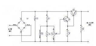
This Power supply circuit is powered by 12 volt AC power supply rectifier diodes form VD1 … VD4, included in a bridge circuit and the rectified voltage stabilizer – capacitors CI, C2, zener VD5 and transistors VT1 and VT2. Voltage power supply output from 0 to 12 regulate the variable resistor R2. The highest current given up power supply to the load (300 mA) is limited to permissible direct current rectifier diodes.
In the rectifier diodes can be used D226 or D7 with any letter index. Variable resistor R2 – with a power switch, it is desirable to group A, to its scale, on which set the output voltage of the power supply was equal numbered. In the stabilizer instead of transistor MP39 MP40 transistors can be used … MP42, and instead of P213 – P214 … P217 transistors, P201, P4 with any letter indices. The gain of transistors must be at least 15. Zener diode D813 can be replaced by zener diodes D811, D814D D814G or. The maximum stress on the power supply output voltage will correspond to the stabilization is used to block the zener. Scale of the resistor R2 should calibrate for exemplary voltmeter connected to the output terminals of the block.
(View)
View full Circuit Diagram | Comments | Reading(1575)
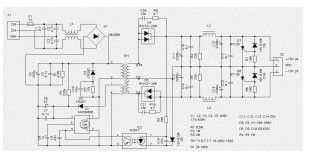
± 60 Volt Switching Power Supply for PA
Published:2013/3/22 2:44:00 Author:Ecco | Keyword: ± 60 Volt , Switching Power Supply, PA
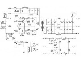
The main part of any amplifier is the power supply. It is clear that to obtain a high output 12-volt battery is not enough. Therefore, we must first create a voltage converter, which enables a bipolar supply +-60V with a capacity of no less than 400W. Digging on the forum found a fairly simple and relatively good scheme.
The brain of this converter is a chip TL494NC, it creates pulses of a given frequency. Frequency set elements R1 and C8. Then these pulses hit the transistors VT1, VT2, which are the control keys for the output transistors. Alternately opening, the output transistors in the primary winding creates an alternating current of high frequency. The transformer increases the voltage to 60V specified, then the current is rectified by a diode bridge. Inductors and capacitors smooth the ripple and high frequency interference. The transformer is wound on a ferrite ring glued two rings size 45 * 28 * 8 marks NM2000. All faces of the ring rounding a file, then wrapped a rag trance tape.
(View)
View full Circuit Diagram | Comments | Reading(3443)
Power Supply for Simple high-quality Tube amplifier class “A”
Published:2013/3/22 2:43:00 Author:Ecco | Keyword: Power Supply , Simple high-quality Tube , amplifier, class “A”
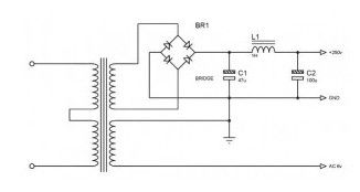
Thispower supplycircuit,is partof a series of Simple high-quality Tubeamplifierclass “A”. Or maybe itcan be applied toother devices.
(View)
View full Circuit Diagram | Comments | Reading(794)
Stabilized power supply +40 V, 1.2 A
Published:2013/3/22 2:42:00 Author:Ecco | Keyword: Stabilized power supply, +40 V, 1.2 A
View full Circuit Diagram | Comments | Reading(838)
60 Volt PBX Power Supply
Published:2013/3/22 2:37:00 Author:Ecco | Keyword: 60 Volt, PBX , power Supply
This stabilizer was designed to supply the PBX (Private branch exchange) up to 10 rooms. Input voltage +65 VAC, Output voltage 55 … 65 V, load current 100 mA. (View)
View full Circuit Diagram | Comments | Reading(1004)
Small Size Power Supply 5-12V
Published:2013/3/22 2:36:00 Author:Ecco | Keyword: Small Size, Power Supply, 5-12V
The proposed unit is designed for AC power small electronic devices (handheld radios, tape recorders, watches, etc.). The output voltage can be selected within the range of 5 to 12 V. One of the advantages of unit – small size: all its parts are placed in the body … mains plug.
(View)
View full Circuit Diagram | Comments | Reading(867)
| Pages:140/2234 At 20121122123124125126127128129130131132133134135136137138139140Under 20 |
Circuit Categories
power supply circuit
Amplifier Circuit
Basic Circuit
LED and Light Circuit
Sensor Circuit
Signal Processing
Electrical Equipment Circuit
Control Circuit
Remote Control Circuit
A/D-D/A Converter Circuit
Audio Circuit
Measuring and Test Circuit
Communication Circuit
Computer-Related Circuit
555 Circuit
Automotive Circuit
Repairing Circuit