
Circuit Diagram
Index 135
Monostable multivibrator circuit diagram
Published:2013/3/25 2:49:00 Author:Ecco | Keyword: Monostable multivibrator
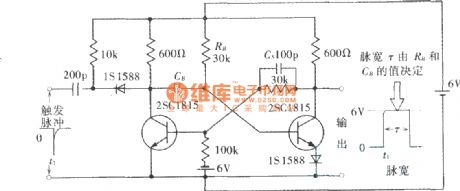
Monostable multivibrator circuit diagram is shown as figure.
(View)
View full Circuit Diagram | Comments | Reading(1323)
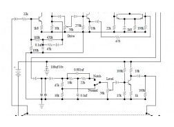
Orange 125MK3 Guitar Mods
Published:2013/3/26 3:45:00 Author:Ecco | Keyword: Orange , Guitar Mods
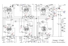
This document contains schematic diagram of Orange 125MK3 including the guitar preamp section, feedback and power amplifier section.
(View)
View full Circuit Diagram | Comments | Reading(774)
Tube Head
Published:2013/3/26 3:44:00 Author:Ecco | Keyword: Tube Head
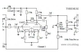
This is a simple and low cost Tube Head Vacuum Tube pre-amp circuit designed bu PAiA electronics: Vcc – Pin 1 IC1 +12v – Pin 8 IC2, IC3, IC4 -12v – Pin 4 IC2, IC3, IC4 Ground – Pin 8 IC1 IC1 – 4049 CMOS Hex Inverting Buffer IC2
(View)
View full Circuit Diagram | Comments | Reading(1873)
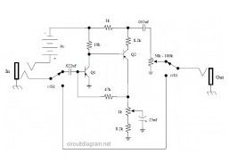
Small Audio Booster
Published:2013/3/26 3:43:00 Author:Ecco | Keyword: Audio Booster
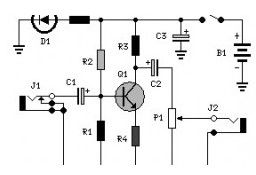
Here the simple, low cost and easy audio booster circuit. It uses a transistor of 2N3392 ad the main amplifier. Component List: R1 = 47K R2 = 470K R3 = 10K R4 = 560R R5 = 270R C1 = 0.1uF/25v C2 = 3.3uF/25v C3 = 470uF/25V P1 = 100K Q1 = 2N3392 D1 = 5mm.
(View)
View full Circuit Diagram | Comments | Reading(1339)
M66T Melody Generator
Published:2013/3/26 3:40:00 Author:Ecco | Keyword: Melody Generator
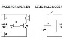
This is the very simple way to play a song with single 1.5 battery. You can build this circuit for gift acceccories. When the gift opened, then a song will be played.. It’s easy and cheap right..? . It just use a single small chip which will generate a song which already planted inside the chip.
(View)
View full Circuit Diagram | Comments | Reading(1079)
Telephone Amplifier using LM386
Published:2013/3/26 3:39:00 Author:Ecco | Keyword: Telephone Amplifier
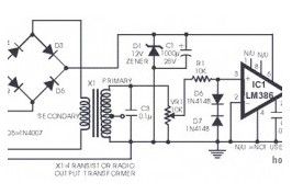
The following diagram is the circuit diagram of telephone amplifier, build based small amplifier IC LM386. This is a easy build telephone amplifier There is no extra electrical power supply required to power up the telephone amplifier circuit, as it draws power from the telephone line itself. The amplifier will supply fairly very good volume for the telephone conversation to be effectively heard in a living room.
(View)
View full Circuit Diagram | Comments | Reading(1379)
5 Band Graphic Equaliser
Published:2013/3/26 3:38:00 Author:Ecco | Keyword: 5 Band, Graphic Equaliser
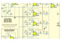
This is the diagram of 5 band graphic equaliser circuit. The circuit is based on operational amplifier, the NE5532 or LM833 is the right choice for low cost op-amp chip with fairly good quality output. Each IC contains dual op-amps circuit, so you will need 4 ICs of NE5532 or LM833 to build this 5 band graphic equaliser.
(View)
View full Circuit Diagram | Comments | Reading(993)
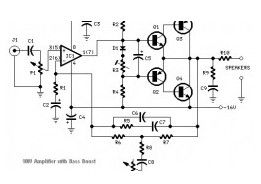
16W Bridge Amplifier using LM383
Published:2013/3/26 3:38:00 Author:Ecco | Keyword: 16W Bridge Amplifier
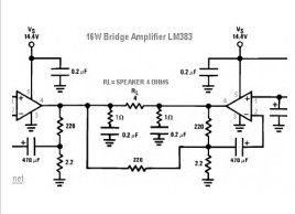
The following diagram is 16W audio amplifier circuit. The circuit built based 2 pieces of power IC LM383 in bridge connection, so this amplifier is an bridge amplifier. This is an old amplifier, LM383 is discontinued, so this LM383 might be difficult to find. You can use ECG1232, TDA2002 or TDA2003 as the replace for LM383.
(View)
View full Circuit Diagram | Comments | Reading(1881)
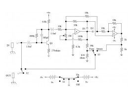
Transistored 10W Audio Amplifier
Published:2013/3/26 3:36:00 Author:Ecco | Keyword: Transistored , 10W, Audio Amplifier
Build based operational amplifier NE5532 and a couple of power transistor TIP41A / TIP42A, this audio amplifier circuit has capability to deliver up to 10W audio power output into 8 ohm speaker.. Amplifier Parts list: P1 22K = Log.Potentiometer P2 = 100K Log.
(View)
View full Circuit Diagram | Comments | Reading(1640)
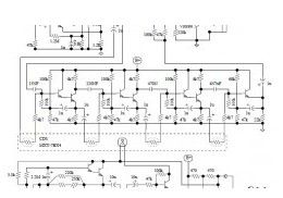
MOSFET Linear Amplifier 300W/50MHz
Published:2013/3/26 3:36:00 Author:Ecco | Keyword: MOSFET Linear Amplifier, 300W/50MHz
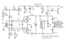
This MOSFET RF Linear Amplifier has capability to deliver up to 300W for 50MHz. The circuit built based the couple of MOSFET ARF448A and ARF448A.
(View)
View full Circuit Diagram | Comments | Reading(4319)
TDA8929T Class-D Audio Power Amplifier
Published:2013/3/26 3:35:00 Author:Ecco | Keyword: Class-D , Audio Power Amplifier
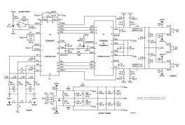
The following diagram is the circuit diagram of Class-D audio power amplifier which built based on power chip TDA8929T. About TDA8929T: The power IC TDA8929T is the controller of a two-chip set for a high efficiency class-D audio power amplifier system. The system is divided into two chips: TDA8929T; the analog controller chip inside a SO24 package TDA8926J/ST/TH or TDA8927J/ST/TH.
(View)
View full Circuit Diagram | Comments | Reading(1851)
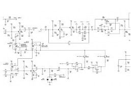
Electro-Harmonix Small Stone Phaser Guitar Effect
Published:2013/3/26 3:34:00 Author:Ecco | Keyword: Electro-Harmonix , Small Stone Phaser, Guitar Effect
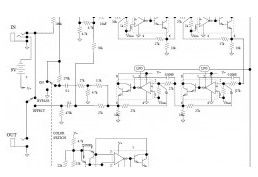
This is the schematic diagram of Electro-Harmonix Small Stone Phaser guitar effect pedal. The Small Stone is somewhat special in applying Operational Transconductance Amplifiers (OTA’s) for phase shift stages rather of opamps with variable resistors. All of the IC’s are house marked EH1048, but could be replaced with CA3094 that is a combination of an OTA equal with the CA3080 as well as a darlington emitter follower.
(View)
View full Circuit Diagram | Comments | Reading(2943)
Electro Harmonix Graphic Equalizer
Published:2013/3/26 3:17:00 Author:Ecco | Keyword: Electro Harmonix , Graphic Equalizer
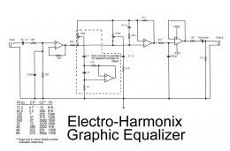
This is the diagram od electro-harmonix graphic equalizer. You can specify the number of channels according to your needs. You just need to parallel the components: C1, C2, R1, an om-amp, Potensiometer and a 470 ohm resistor. The frequency to be boost decided by C1, C2 and R1. See the diagram for the C1, C2 and R1 combination versus the frequency.
(View)
View full Circuit Diagram | Comments | Reading(1172)
DOD FX75 Flanger Guitar Effect Pedal
Published:2013/3/26 3:16:00 Author:Ecco | Keyword: DOD , Flanger Guitar, Effect Pedal
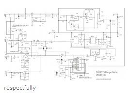
This is the circuit diagram of DOD FX75 Flanger guitar effect pedal. The circuit drawn by Fabian P. Hartery Components description: CD4007 dual complementary pair with inverter; (RCA) TL022C low power dual operating amplifier; (texas instruments) MN3007 audio signal delay, 1024 stage low noise BBD (5.12-51.2 msec delay) MN3101 clock generator for Bucket Brigade Device/BBD MN3101/MN3007 manfufactured by Panasonic.
(View)
View full Circuit Diagram | Comments | Reading(1419)
Gibson RD Artist Guitar
Published:2013/3/26 3:14:00 Author:Ecco | Keyword: Gibson RD Artist Guitar
The following diagram is the schematic of Gibson RD Artist bass guitar Circuit Notes: Both compression and expansion effects are determined by the lead pickup output only. I and O in the design diagram refer to inner and outer connections for the specific plug / jack. P and J in the design diagram refer to plugs and jacks respectively.
(View)
View full Circuit Diagram | Comments | Reading(1131)
4W Stereo Amplifier using LM2877
Published:2013/3/26 3:14:00 Author:Ecco | Keyword: 4W Stereo Amplifier
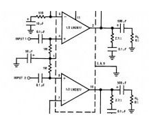
This is the diagram of 4W stereo power amplifier built based stereo power IC LM2877 with a few of external components. The circuit required single power supply with voltage range of 6VDC – 24VDC. Heatsink is a must to prevent over heating on the IC.
(View)
View full Circuit Diagram | Comments | Reading(1007)
Vox Tone Bender Pedal
Published:2013/3/26 3:13:00 Author:Ecco | Keyword: Vox Tone Bender Pedal
This is the circuit diagram of Vox Tone Bender Pedal. The circuit is very similar to Fuzz Face pedal. The Vox ToneBender will have a lot more treble response than the Fuzz Face…maybe to help brighten up those characteristically “dark” sounding British amps some.
(View)
View full Circuit Diagram | Comments | Reading(939)
Univox Super-Fuzz Pedal
Published:2013/3/26 3:12:00 Author:Ecco | Keyword: Univox Super-Fuzz Pedal
This is the circuit diagram of Univox Super-Fuzz Pedal. This pedal is actually a 69-to-early 70’s design that consists of two special capabilities. They are the octave generation effect from the differential-pair-with-collectors -tied-together along with the option of just a clipping amplifier or a 1kHz notch for different sounds.
(View)
View full Circuit Diagram | Comments | Reading(1195)
UniVibe Pedal
Published:2013/3/26 3:11:00 Author:Ecco | Keyword: UniVibe Pedal
The Univibe is actually a footpedal-operated phaser or phase shifter for generating chorus and vibrato simulations for electric organ or guitar. It was introduced in the 1960s by Shin-ei, and was intended to emulate the “Doppler sound” of a Leslie speaker.
(View)
View full Circuit Diagram | Comments | Reading(1460)
Octave Fuzz Pedal
Published:2013/3/26 3:10:00 Author:Ecco | Keyword: Octave Fuzz Pedal
Here the circuit diagram of octave fuzz guitar effect pedal. This guitar effect unit is great sounding octave fuzz, with an optional mode of just fuzz. The fuzz is really a absolutely rectified signal and is fairly chewy.
(View)
View full Circuit Diagram | Comments | Reading(1551)
| Pages:135/2234 At 20121122123124125126127128129130131132133134135136137138139140Under 20 |
Circuit Categories
power supply circuit
Amplifier Circuit
Basic Circuit
LED and Light Circuit
Sensor Circuit
Signal Processing
Electrical Equipment Circuit
Control Circuit
Remote Control Circuit
A/D-D/A Converter Circuit
Audio Circuit
Measuring and Test Circuit
Communication Circuit
Computer-Related Circuit
555 Circuit
Automotive Circuit
Repairing Circuit