
Circuit Diagram
Index 1400
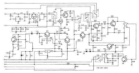
1O_METER_DSB_TRANSMITTER
Published:2009/6/19 3:54:00 Author:May
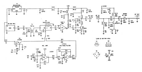
A DSB transmitter is much cheaper to build than an SSB transmitter because no filter or phasing networks are required. This circuit produces up to 1-W output on the 10-meter band. The frequency 28.322 MHz is used, which is a commonly available clock frequency crystal. CW operation is also provided. A doubly balanced mixer assembly is used as a modulator and CW keyer (View)
View full Circuit Diagram | Comments | Reading(2032)
DIGITAL_RELATIVE_HUMIDITY_GAUGE
Published:2009/6/19 3:53:00 Author:May
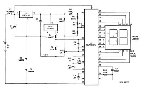
Sensor SEN1 outputs a dc voltage that varies linearly with relative humidity. This dc voltage is fed through R1 and R2 to A/D converter chip U2. Zero set is performed with R4. The LCD display is calibrated with R7 to read 0 to 100 percent. (View)
View full Circuit Diagram | Comments | Reading(1461)
15_V_LOGARITHMIC_LIGHT_LEVEL_METER
Published:2009/6/19 3:52:00 Author:May
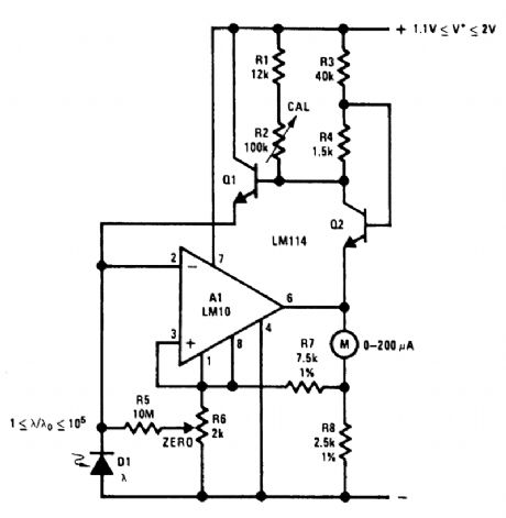
A portable light-level meter with a five-decade dynamic range is shown. The circuit is calibrated at mid-range with the appropriate illumination by adjusting R2 such that the amplifier output equals the reference and the meter is at center scale. The emitter-base voltage of Q22 will vary with supply voltage; so R4 is included to minimize the effect on circuit balance. If photocurrents less than 50 nA are to be measured, it is necessary to compensate the bias current of the op amp.The logging slope is not temperature compensated. With a five-decade response, the error at the scale extremes will be about 40% (a half stop in photography) for a ±18℃ temperature change.If temperature compensation is desired, it is best to use a center-zero meter to introduce the off-set, rather than the reference compensation. It can be obtained by making the resistor in series with the meter a copper wire-wound unit.If this design is to be used for photography, it is important to remember that silicon photodiodes are sensitive to near-infrared light, whereas ordinary film is not. Therefore, an infrared-stop filter is called for. A blue-enhanced photodiode or an appropriate correction filter would also produce best results. (View)
View full Circuit Diagram | Comments | Reading(652)
FURNACE_FUEL_MISER_5
Published:2009/6/19 3:51:00 Author:May
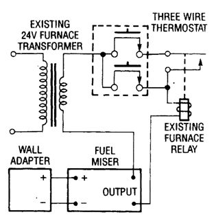
Some oil-fired systemt use threewire thermostats to control the operation of the burner motor and ignition system by activaring a relay. This is a typical installation for such systems. (View)
View full Circuit Diagram | Comments | Reading(608)
HUMIDITY_MONITOR
Published:2009/6/19 3:51:00 Author:May
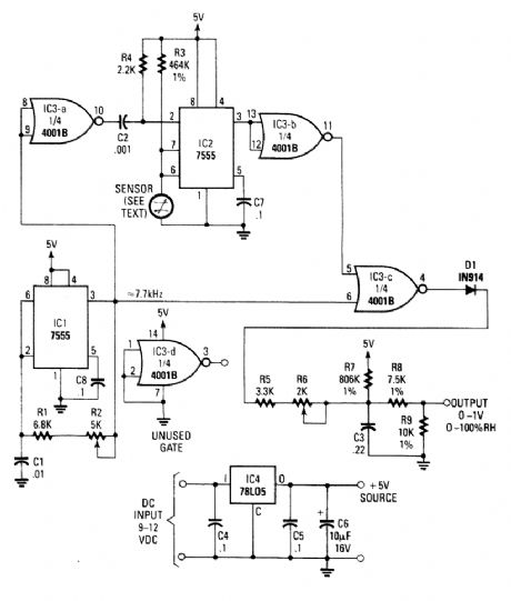
This circuit uses a Phillips capacitive humidity sensor that has a AC variation of 45 pF over 0 to 100 pf, RH. IC2 is an oscillator whose frequency is determined by the RH sensor, It is compared to fixed oscillator, and tie difference frequency is taken by IC3C and rectified, outputting a 0- to 1-V signal for RH between 0 and 100%. (View)
View full Circuit Diagram | Comments | Reading(1363)
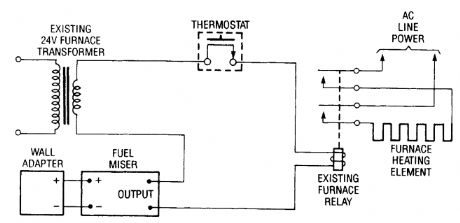
FURNACE_FUEL_MISER_4
Published:2009/6/19 3:49:00 Author:May
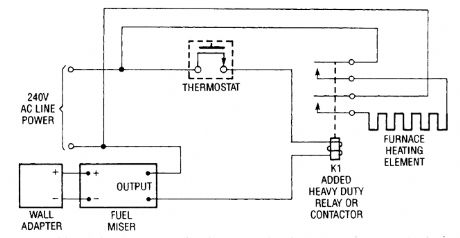
Electric-heuting systems that do not contain a low-current thermostat (as in the prerious installation), use a heavy-duty thermostut thtu directly feeds current to the heating element.For such systems, it will be necessary to install a heavy-duty relay (K1 in this exumple) to control the heavy heating-element current. (View)
View full Circuit Diagram | Comments | Reading(631)
WHEEL_OF_FORTUNE
Published:2009/6/19 3:48:00 Author:May
The oscillation of Q2 is amplified by Q3 and fed to Johnson counter IC1. The output of IC1 drives the LEDs in sequence to give the impression of a spinning red ball. (View)
View full Circuit Diagram | Comments | Reading(4)
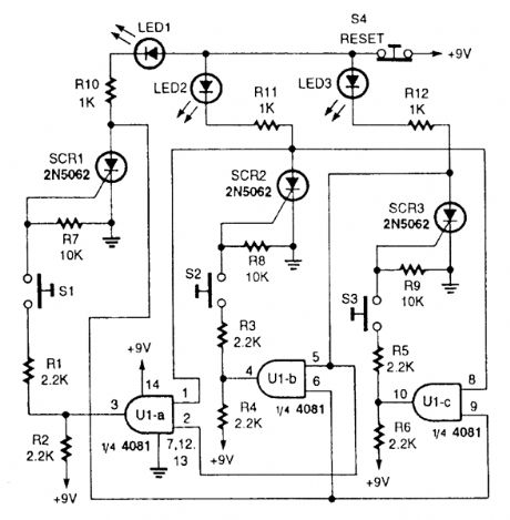
ANALOG_FIRST_RESPONSE_MONITOR
Published:2009/6/19 3:47:00 Author:May
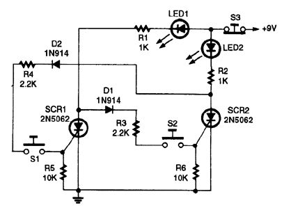
The analog first-response monitor is built around a pair of cross-coupled SCRs, each of which receives its gate trigger current from the anode of the other SCR. (View)
View full Circuit Diagram | Comments | Reading(790)
FURNACE_FUEL_MISER_3
Published:2009/6/19 3:47:00 Author:May
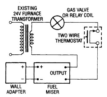
This drawing shows the Fuel Miser connecled in series wlith the thermostat of a two-wire gas furnace that's powered by c 24-volt transformer. (View)
View full Circuit Diagram | Comments | Reading(688)
FIRST_RESPONSE_MONITOR_II
Published:2009/6/19 3:46:00 Author:May
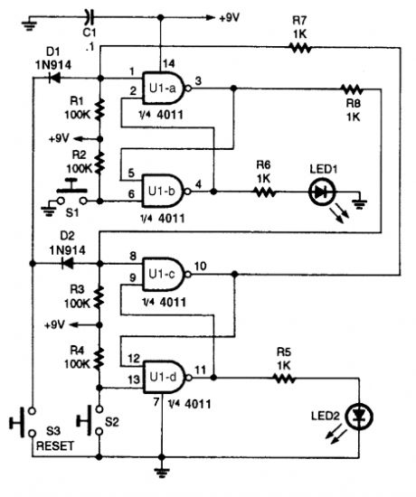
Two interlocking flip flops are used to detect the first of two inputs,but a logical-level signal can be substituted. (View)
View full Circuit Diagram | Comments | Reading(671)
1750_METER_TRANSVERTER
Published:2009/6/19 3:46:00 Author:May
This circuit was described in a recent edition of an amateur radio magazine. It allows operation in the 160- to 190-kHz band with up to 1 W (license free) in any mode (CW/SSB/FM, etc.). It consists of a receiving converter for 5 kHz to 450 kHz and a transmitting converter to convert the 3.66- to 3.69-MHz (80 meter) range to 160 to 190 kHz. A 12- to 24-V power supply can be used. (View)
View full Circuit Diagram | Comments | Reading(1365)
The compensation circuit of op amp output capacitor
Published:2011/6/27 21:52:00 Author:Rebekka | Keyword: Op amp output capacitor, Compensation circuit
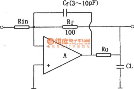
Put a resistance Ro at the output terminal of the series. The load capacitance CL and amplifying circuit is separated, it is shown in figure, connect the feedback resistance Rf in the back of the Ro. This can compensate the dc attenuation. The feedback capacitor Cf will reduce the high frequency closed-loop voltage magnification. The method of selecting Cf is: Make amplifier circuit of the unit gain the RongKang Xcf frequency fT 10, Rf/Xf = l / (2) fTCf PI. Usually, Ro = 50 ~ 200 Ω, Cf is 3 ~ 10 pF. It is shown in figure, the op-amp output capacitance of the compensation circuit diagram.
(View)
View full Circuit Diagram | Comments | Reading(1474)
FURNACE_FUEL_MISER_2
Published:2009/6/19 3:45:00 Author:May
Electric-heating systems may or may not use a relay in the thermostat c ircuit. Those that do have a relay can be controlled by the Fuel Miser by wiring its output circuit in series with the relav coil connections as shown here. (View)
View full Circuit Diagram | Comments | Reading(683)
DIGITAL“FIRST_TO_RESPOND”BOX
Published:2009/6/19 3:44:00 Author:May
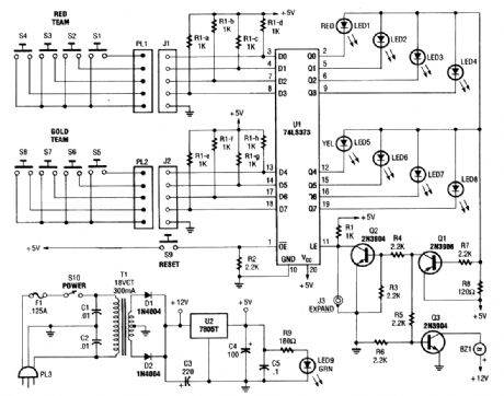
This device is useful for quizzes and games to determine first response. U1 is an octal D type latch IC, an 74LS373.When a button is pushed, this circuit lights the corresponding LED. Q1 conducts, sounding an alarm (BZ1) connected to driver Q3, and Q1 supplies bias to Q2, disabling the rest of the latches in U1. (View)
View full Circuit Diagram | Comments | Reading(929)
FURNACE_FUEL_MISER_1
Published:2009/6/19 3:43:00 Author:May
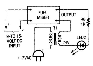
When the circuit is working properly the output circuitry can be checked using a 24-volt step-down transformer, a lk resistor, and an LED. Together those components simulate the load that the Fuel Miser sees during normal operation. (View)
View full Circuit Diagram | Comments | Reading(705)
voltage follower circuit composed of the μA709
Published:2011/6/27 20:49:00 Author:Rebekka | Keyword: voltage follower
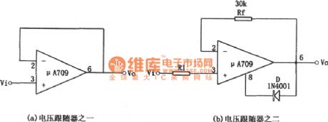
Figure (a) shows the circuit of the voltage follower. It is a special case of the inverting amplifier circuit. The basic relationship of the circuit is: Vi + Vis = Vo Vo =-AVis formula: A - open loop voltage gain operation; Vis - pure op amp input voltage; In the circuit, when the voltage amplitude of the input signal increased to the op amp's positive supply voltage, the deadlock may occur, ie the output signal will not work properly which is due to the internal positive feedback op amp has a parasitic oscillation. To prevent this phenomenon, you can use (b). (View)
View full Circuit Diagram | Comments | Reading(483)
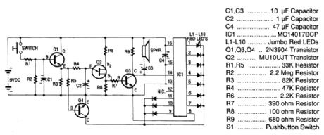
ELECTRONIC_ONE_ARM_BANDIT
Published:2009/6/19 3:42:00 Author:May
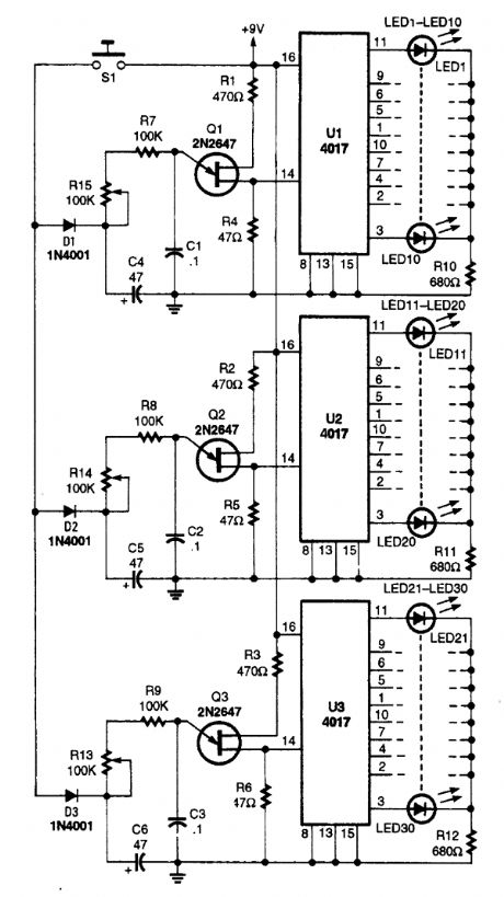
The one-arm bandit circuit is made up of three clock circuits and three counter/readout circuits.A single roll switch, 51, turns on all three clocks at the same time. When S1 is closed, capacitors C4, C5, and C6 are charged through D31, D32, and D33 to about 8 V. After S1 is released, the three clocks run, taking energy from the three charged capacitors. As the capacitors discharge, the three clocks begin to slow down, producing the effect of the drums in a mechanical bandit slowing to a stop.The 4017's 10-output LEDs can be numbered or designated as apples, cherries, bells, wild cards, or anything you like to make the game more interesting. Additional logic circuitry can be added to the 4017 outputs to sound an alert or turn on a light when any three numbers or output items match.Three potentiometers, R12, R13, and R14, can be varied for each roll to change the clock's fre-quency and the roll rate. (View)
View full Circuit Diagram | Comments | Reading(2489)
NANOAMMETER
Published:2009/6/19 3:42:00 Author:May

Potentiometer R2 provides an electrical meter zero by forcing input offset voltage Vos, to zero. Full-scale meter deflection is set by R1. Both RI and R2 only need to be set once for each op amp and meter combination. For a 50-μA 2-kΩ meter movement, R1 should be about 4kΩ to give full-scale meter deflection in response to a 300-mV output voltage. Diodes Dl and D2 provide full input pro-tection for overcurrents up to 75 mA.With an R, resistor value of 1.5 MΩ, the circuit becomes a nanoammeter with a full-scale reading capability of 100 nA. Reducing Rf, to 3 kΩ in steps, as shown in the figure increases the full-scale de-flection to 100μA, the maximum for this circuit configuration. The voltage drop across the two input terminals is equal to the output voltage(Vo)divided by the open loop gatn. Assume that an open loop gain of 10,000 gives an input voltage drop of 30μV or less. (View)
View full Circuit Diagram | Comments | Reading(2)
ELECTRONIC_COIN_TOSS
Published:2009/6/19 3:40:00 Author:May
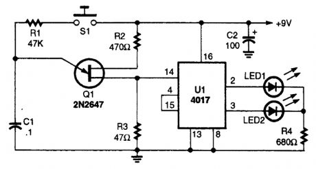
Integrated circuit U1 is connected in a two-stage counter circuit that counts one-two over and over as long as clock pulses enter pin 14 of the 4017. When the clock pulses stop, one of the LEDs will remain on, indicating the last even or odd count. Designate one LED as heads and the other as tails and you have an electronic coin flipper. (View)
View full Circuit Diagram | Comments | Reading(1303)
THREE_NPUT_FIRST_RESPONSE_MONITOR
Published:2009/6/19 3:39:00 Author:May
View full Circuit Diagram | Comments | Reading(840)
| Pages:1400/2234 At 2013811382138313841385138613871388138913901391139213931394139513961397139813991400Under 20 |
Circuit Categories
power supply circuit
Amplifier Circuit
Basic Circuit
LED and Light Circuit
Sensor Circuit
Signal Processing
Electrical Equipment Circuit
Control Circuit
Remote Control Circuit
A/D-D/A Converter Circuit
Audio Circuit
Measuring and Test Circuit
Communication Circuit
Computer-Related Circuit
555 Circuit
Automotive Circuit
Repairing Circuit