
Circuit Diagram
Index 1924
FM wireless microphone circuit
Published:2011/5/8 4:53:00 Author:John | Keyword: FM wireless microphone circuit
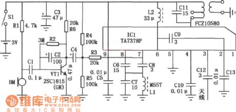
FM wireless microphone makes use of Manifold TA7378 of FM radio. It has few external components. So it is simple to make and is stable, which is especially suitable for production of radio enthusiasts. The specific circuit for FM wireless microphone is shown in the figure. ICl (TA7378P) includes RF amplifier, mixer, buffer amplifier, local oscillator circuit and the bias voltage regulator circuit. The circuit skillfully combines internal circuits. It uses the oscillator circuit and the AFC (Automatic Frequency Control) in order to constitute a variable capacitor circuit, aiming to generate FM (frequency modulation) wave. In order to reduce external effects, it is suitable to add a buffer amplifier between the oscillations and a mixer. Finally, the RF amplifier amplifies to transmit FM radio through the antenna. (View)
View full Circuit Diagram | Comments | Reading(3568)
PIC16C57-RC / P communication single-chip microcomputer integrated circuit diagram
Published:2011/5/6 1:01:00 Author:Ecco | Keyword: communication, single-chip, microcomputer , integrated circuit
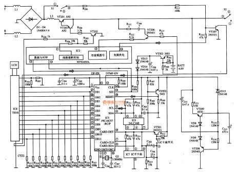
PIC16C57-RCT is communication single-chip microcomputer integrated circuit, which is widely used in Qiao Xing series of IC card management telephone. 1. Function descriptionPIC16C57-RC integrated circuit includes pulse and dual-tone dialing circuit, memory data and the clock circuit, IC card connector data and clock circuit, reset circuit, dial-up data and the clock circuit, the LCD display decoding circuit and driving circuit and some other auxiliary functions circuit. 2. Pin functions and data PIC16C57-RC uses 28-pin dual in-line package, the pin functions and data are listed in Table. PIC16C57-RC / P IC pin functions and data 3. The typical IC card management system application circuit composed of the PIC16C57-RC / P IC is shown as the chart. PIC16C57-RC / P IC Typical Application Circuit
(View)
View full Circuit Diagram | Comments | Reading(5633)
Temperature control circuit with the temperature range of -10℃ to 20℃
Published:2011/5/9 19:51:00 Author:TaoXi | Keyword: Temperature control, temperature range
Related components PDF download:
TCA965BC327BCW80
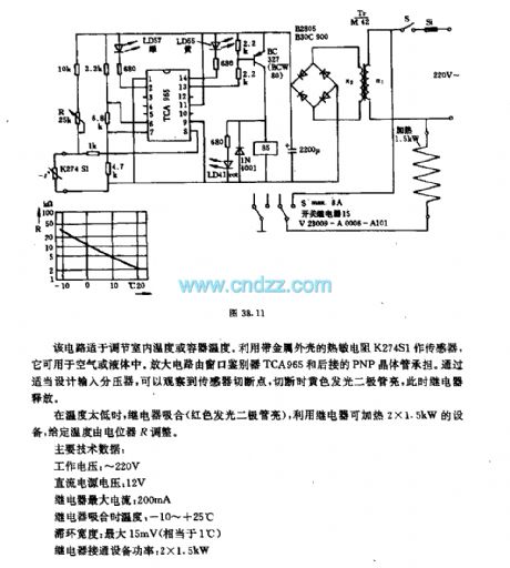
This circuit can be used to adjust the temperature of room or container. It uses the thermistor K274S1 (with the metal shell) as the sensor, and it can be used in the air or liquid. The amplifier circuit is assumed by the window discriminator TCA965 and the rear PNP transistor. By designing the input divider, we can observe the cut-off point of the sensor, when you cut off it, the yellow LED will turn on, and the relay will release.
If the temperature is too low, the relay will turn on (red LED turns on), we can heat the 2x1.5kW equipment by using the relay, the given temperature is adjusted by the potentiometer R.
Main technical data:
Operating voltage: 220VDC supply voltage: 12VRelay max current: 200mARelay turn-on temperature: -10 ℃ to +25 ℃Hysteresis width: max 15mV (equivalent to 1 ℃)Relay connection equipment power: 2x1.5kW (View)
View full Circuit Diagram | Comments | Reading(1143)
automatically start air-conditioning circuit with the TC621
Published:2011/5/9 10:39:00 Author:TaoXi | Keyword: automatically start, air-conditioning
Related components (View)
View full Circuit Diagram | Comments | Reading(1190)
TDA16846 pin functions and data circuit
Published:2011/5/8 22:25:00 Author:TaoXi | Keyword: pin functions, data
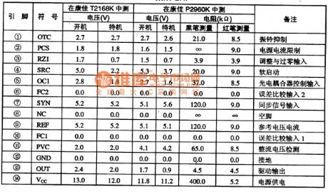
2.Pin functions and data
The TDA16846 can be used in the Konka series TV, and the pin functions and data is as shown in table 61.
Table 61 The pin functions and data of the TDA16846
(View)
View full Circuit Diagram | Comments | Reading(1222)
TDA4661, TDA4661V2 integrated block internal box circuit
Published:2011/5/6 22:20:00 Author:TaoXi | Keyword: integrated block, internal box
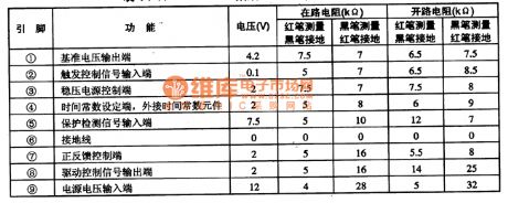
1.Pin functions and data
The TDA4601 is in the single 9-pin DIP package, the pin functions and data is as shown in table 11.
Table 11 TDA4601 TDA4601 pin-5's functions and data
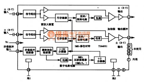
1.Features
The TDA4661 and TDA4661V2 are used as the geometry adder (vector sum) according to the color signal standard, to meet the requirements of PAL format decoder: in the NTSC system, it plays the role of comb filter to reduce the cross color interference; in the SECAM system, it plays the role of line memory to ensure that each line exists the (R-Y), (B-Y) color difference signals when it is decoding to complete the right SECAM decoding system role. The block diagram of the circuit is as shown in figure 11.
(View)
View full Circuit Diagram | Comments | Reading(1699)
Temperature control circuit
Published:2011/5/9 20:08:00 Author:TaoXi | Keyword: Temperature, control
Related componts PDF download:
BC251ABC107BBC141
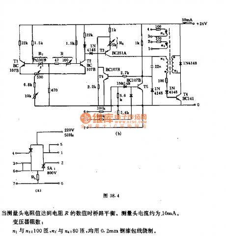
In figure (a), heating resistor RL connects to the 220V AC grid by the SCR. Figure (b) shows the control circuit. In order to measure the temperature, we use the bridge circuit which is composed of the resistance RT (measuring head), R (the given value resistor) and two 1.5kΩ resistors.
When the value of probe resistance is the same as the resistance R, the bridge is in balance. The probe current is about 10mA.
The resistance number of the transformer: n1 and n2: 100 turns, n3 and n4: 80 turns, they are all surrounded by the 0.2mm copper-paint wire. (View)
View full Circuit Diagram | Comments | Reading(1049)
The typical application circuit diagram of PT2124 IC
Published:2011/5/9 3:42:00 Author:Ecco | Keyword: typical application circuit , IC
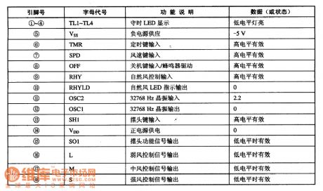
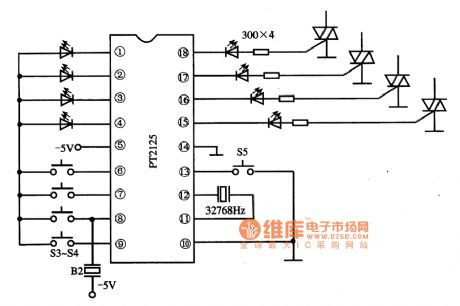
PT2125 is the fan monolithic microcomputer integrated circuit, which is widely used in various types of program control circuits. PT2125 IC uses the 18-pin dual in-line package, the pin functions and data are listed in table, it usually forms remote control fan system with the BA5101/A5201, the typical application circuit is shown as teh chart.
(View)
View full Circuit Diagram | Comments | Reading(2011)
The proportion of time division system remote control circuit diagram
Published:2011/5/9 0:59:00 Author:Rebekka | Keyword: Remote control system , proportional division

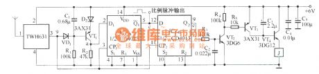
The proportion of time division system remote code transmission circuit:
The proportion of time division system remote control receiver decoding circuit:
(View)
View full Circuit Diagram | Comments | Reading(858)
Mini wireless monitoring FM transmitter circuit No.2
Published:2011/5/9 4:07:00 Author:TaoXi | Keyword: Mini, wireless, monitoring, FM transmitter
The Mini wireless monitoring FM transmitter circuit No.2. (View)
View full Circuit Diagram | Comments | Reading(784)
Mini wireless monitoring FM transmitter circuit
Published:2011/5/9 4:08:00 Author:TaoXi | Keyword: Mini, wireless, monitoring, FM transmitter
The Mini wireless monitoring FM transmitter circuit. (View)
View full Circuit Diagram | Comments | Reading(750)
temperature alarm circuit
Published:2011/5/9 19:17:00 Author:TaoXi | Keyword: temperature, alarm
Related components PDF download:
TAA3761TAA2176A (View)
View full Circuit Diagram | Comments | Reading(649)
Vibration sensing voice FM wireless transmitter circuit (ND-2, TM-801A)
Published:2011/5/9 4:11:00 Author:TaoXi | Keyword: Vibration sensing, voice FM, wireless transmitter
The Vibration sensing voice FM wireless transmitter circuit (ND-2, TM-801A). (View)
View full Circuit Diagram | Comments | Reading(868)
Simple temperature control circuit
Published:2011/5/9 19:00:00 Author:TaoXi | Keyword: Simple, temperature control
The Simple temperature control circuit (View)
View full Circuit Diagram | Comments | Reading(462)
Livestock fence-breaking alarm wireless transmitter circuit
Published:2011/5/9 4:10:00 Author:TaoXi | Keyword: Livestock, fence-breaking, wireless transmitter
The Livestock fence-breaking alarm wireless transmitter circuit. (View)
View full Circuit Diagram | Comments | Reading(753)
lOW sound and light siren circuit diagram
Published:2011/5/6 4:24:00 Author:Ecco | Keyword: lOW, sound , light s, iren

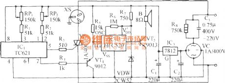
lOW sound and light siren circuit diagram is shown as the chart. The circuit can produce high-intensity alarm which can be used as anti-theft alarm. When the power is switched on the alarm system, VD1 is flashing, while it outputs the pulse square wave on R1 resistor, after gets triangular wave by passing R2, VD2, C1 network, IC is a 555 time base circuit, and it forms voltage-controlled oscillator. R3, R4 and C3 are the timing components. The output variable tone signal is amplified by the VT under the control of the triangular wave to promote the speaker, the output power closes to l0W. Adjusting R1 can change the triangle wave amplitude of C1, changing W1 can adjust the volume. Figure (b) is printed installation diagram.
(View)
View full Circuit Diagram | Comments | Reading(1564)
Household constant temperature control circuit
Published:2011/5/9 18:45:00 Author:TaoXi | Keyword: Household, constant temperature control
The Household constant temperature control circuit is as shown: (View)
View full Circuit Diagram | Comments | Reading(426)
children anti-lost reminder transceiver module composed of the RCMlA/RCMlB
Published:2011/5/9 4:19:00 Author:TaoXi | Keyword: children, anti-lost reminder, transceiver module
This circuit is composed of the transmitter and receiver, the core components are the RCM1A and RCM1B. (View)
View full Circuit Diagram | Comments | Reading(689)
STR-6654 thick film switching power supply integrated circuit diagram
Published:2011/5/6 4:47:00 Author:Ecco | Keyword: thick film , switching, power supply , integrated circuit
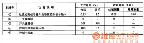
STR-6654 is the switching power supply thick film integrated circuit produced by Sanyo, it is widely used in rear projection color TV (for example, Changhong HP Series precision ), DVD players and other switching power supply circuits. 1. Features of functionSTR-6654 IC includes start circuit, driver circuit, switching adjusting tube, over-voltage protection circuit, over-current protection circuit and other ancillary functions circuit. 2. Pin functions and data STR-6654 IC uses 5-foot single-line package, the pin functions and data are listed in Table. The data is measured in Changhong HP Series of precision rear projection color TV. STR-6654 integrated circuit pin functions and data
(View)
View full Circuit Diagram | Comments | Reading(2616)
MN1220 Memory Integrated Circuit
Published:2011/5/8 21:59:00 Author:Sharon | Keyword: Memory, integrated
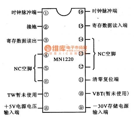
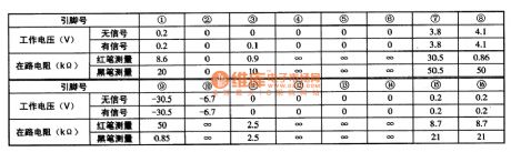
MN1220 is memory integrated circuit produced by Matsushita, widely used in televisions, audio equipment, DVD players and so on. 1. FeaturesMN1220 IC is mainly composed of the memory matrix within the circuit, reset circuit and data input / output interface circuit. 2. Pin functions and dataMN1220 IC is in 16-pin dual in-line package. The pin functions are shown in the figure, and the operating parameters are listed in Table. (View)
View full Circuit Diagram | Comments | Reading(1942)
| Pages:1924/2234 At 2019211922192319241925192619271928192919301931193219331934193519361937193819391940Under 20 |
Circuit Categories
power supply circuit
Amplifier Circuit
Basic Circuit
LED and Light Circuit
Sensor Circuit
Signal Processing
Electrical Equipment Circuit
Control Circuit
Remote Control Circuit
A/D-D/A Converter Circuit
Audio Circuit
Measuring and Test Circuit
Communication Circuit
Computer-Related Circuit
555 Circuit
Automotive Circuit
Repairing Circuit