
Circuit Diagram
Index 1933
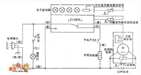
spaceflight BCD-183 fridge circuit diagram
Published:2011/5/8 7:27:00 Author: | Keyword: fridge, circuit
View full Circuit Diagram | Comments | Reading(658)
Constant temperature control circuit compose of the smart temperature sensor DS1620 with three-wire serial interface
Published:2011/5/8 22:38:00 Author:Christina | Keyword: Constant temperature, smart temperature sensor, three-wire serial interface
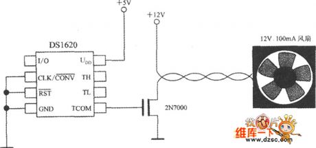
When you use the DS1620 to monitor the temperature of the microprocessor, you can change the chip's cooling condition by turn on or off the fan to achieve the temperature control, the circuit is as shown. The feature is: the TCOM signal gets through the 2N7000-type MOSFET to control the fan, when the chip's surface temperature is t>tH, the fan turns on until t<tL. The main parameters of the 2N7000 are: the drain-source breakdown voltage UDSO=60V, the rated on-state current IT=280mA, the maximum continuous output power PD=830mW. For the high power cooling fan, you can use the 2N7010-type MOSFET, it's IT=13A,PD=1.2W.
(View)
View full Circuit Diagram | Comments | Reading(1275)
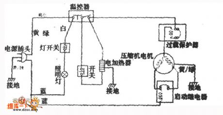
yangzi BCD-188、BCD-202 refrigerator circuit diagram
Published:2011/5/7 21:29:00 Author: | Keyword: refrigerator, circuit
View full Circuit Diagram | Comments | Reading(602)
The typical application circuit diagram of LC906 IC
Published:2011/5/6 3:24:00 Author:Ecco | Keyword: typical application circuit , IC
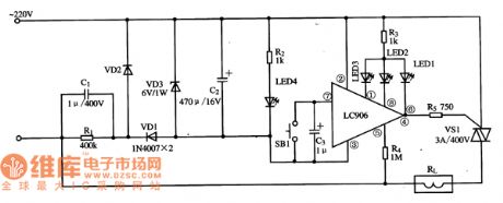
The power adjusting typical application circuit diagram composed of LC906 IC is shown as the chart.
The typical application circuit diagram of LC906 IC is shown as the chart. (View)
View full Circuit Diagram | Comments | Reading(617)
Suspensory Hydraulic Generator Structure Circuit
Published:2011/5/8 10:44:00 Author:Robert | Keyword: Suspensory, Hydraulic Generator, Structure
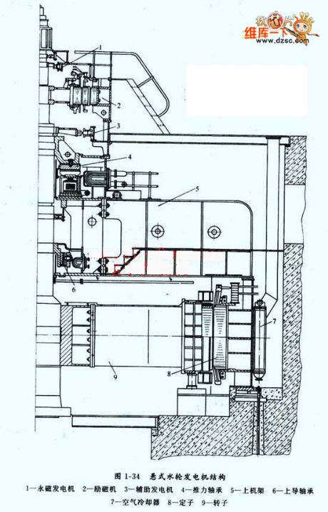
The Suspensory Hydraulic Generator Structure Circuitis shown in the picture below.
Its structure has:
1-permanent magnet generator. 2-Exciter. 3-Auxiliary generator. 4-Thrust bearing. 5-Up Rack. 6-Up connecting bearing. 7-Air cooler. 8-Stator. 9-Rotor.
(View)
View full Circuit Diagram | Comments | Reading(1063)
Simple Pulse Signal Generator Circuit Composed Of 74LS00
Published:2011/5/6 6:34:00 Author:Robert | Keyword: Pulse Signal Generator
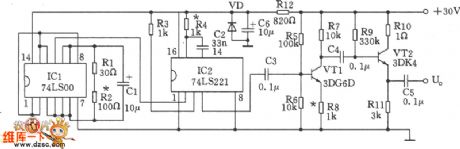
The Simple Pulse Signal Generator Circuit Composed Of 74LS00 is shown in the picture below. This Signal Generator uses mainly two TTL integrated circuit (74LS00) to generate t=4us pulse signal. Its components used is just a few so that it is easy foradjustment andmaintenance.
(View)
View full Circuit Diagram | Comments | Reading(1923)
Direct reading type hygrometer circuit diagram
Published:2011/5/9 2:07:00 Author: | Keyword: Direct reading type, hygrometer
Illustration is direct reading type hygrometer circuit, including RH for chlorinated hammer humidity sensitive resistor. The power supply's humidity measurement bridge is made up by VT1, VT2 and T1 etc and the power supply's oscillation frequency is 250-1000Hz.Bridge output signal through the transformer T2, C3 coupled to the VT3, and the signal amplified by VT3 enters microammeter after bridge rectifiering by VD1-VD4, indicates the relative humidity changeslead to the current changes. By calibrating and Characterizing the humidity on the microampere dial ,it's to be a simple and practical a direct reading hygrometer.
var translatedXML = null;
(View)
View full Circuit Diagram | Comments | Reading(628)
Five uses tri-state audio logic pen (CD4066, 555) circuit diagram
Published:2011/5/6 2:28:00 Author:Ecco | Keyword: Five uses, tri-state, audio , logic pen, 555
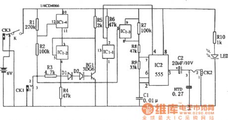
Five uses tri-state audio logic pen (CD4066, 555) circuit diagram is shown as the chart. The circuit is mainly composed of the multivibrator, the four-way switch CD4066 (IC1) and the gate circuit composed of some RC components. Multivibrator is composed of the 555 (IC2) and R7, R8, R9, C1, and its frequency is controlled by IC1-3 on-off state.
(View)
View full Circuit Diagram | Comments | Reading(2399)
Four-channel electronic switch audio mixer circuit
Published:2011/5/6 22:01:00 Author:TaoXi | Keyword: Four-channel, electronic switch, audio mixer
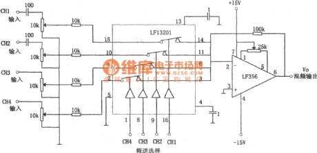
The four-channel electronic switch audio mixer circuit is as shown. The LF13201 is the four-channel analog electronic switch, the LF356 is the low-noise FET input type op amplifier. Four-channel signal is RC coupled or directly coupled by the amplifier, and is added to the electronic switch LF13201's pin-2, pin-7, pin-10 and pin-15, the single-pole double-throw switch is composed of the above pins and the pin-3, pin-6, pin-11, pin-14. The four analog switches are controlled by pin-1, pin-8, pin-9 and pin-16's external control voltage. When the control voltage has high-level voltage, the corresponding switch turns off. The control voltage is provided by the TTL and CMOS driver circuit but not the LF356 and LF13201. (View)
View full Circuit Diagram | Comments | Reading(3960)
Simple second-line logic state discriminator circuit diagram composed of 556
Published:2011/5/6 2:34:00 Author:Ecco | Keyword: Simple, second-line , logic state , discriminator , 556
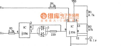
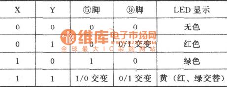
The relationship between LED light with the logic state (View)
View full Circuit Diagram | Comments | Reading(641)
Basic Instrument Amplifier Circuit
Published:2011/5/6 11:11:00 Author:Joyce | Keyword: Basic, Instrument, Amplifier
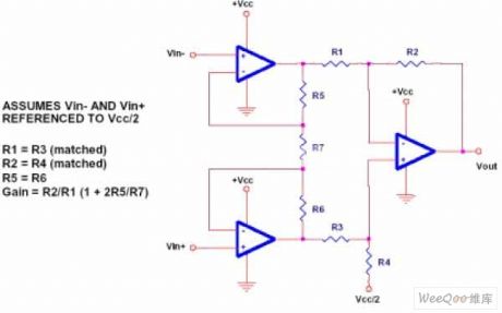
Basic Instrument Amplifier Circuit (View)
View full Circuit Diagram | Comments | Reading(706)
CA3140-composed Broadband Output Amplification Circuit
Published:2011/5/6 11:18:00 Author:Joyce | Keyword: CA3140-composed, Broadband, Output, Amplification
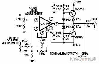
CA3140-composed Broadband Output Amplification Circuit (View)
View full Circuit Diagram | Comments | Reading(3697)
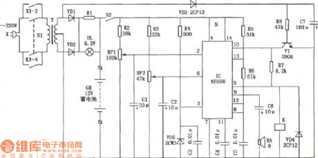
Multi-function remote control circuit (555、LM909)
Published:2011/5/8 9:10:00 Author:TaoXi | Keyword: Multi-function, remote control circuit
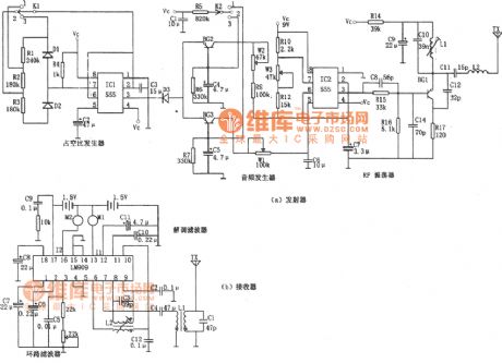
The Multi-function remote control circuit (555、LM909) is as shown:
(View)
View full Circuit Diagram | Comments | Reading(1035)
TA872OAN multi-channel electronic switch integrated circuit
Published:2011/5/6 21:45:00 Author:TaoXi | Keyword: multi-channel, electronic switch
The TA872OAN is designed as one kind of multi-channel electronic switch integrated circuit that can be used in all kinds of video and audio equipment as the multi-channel signal switch.
1.Features
The TA872OAN has the multi-channel electronic switch circuit and the multi-channel 6dB amplifier to amplify the transmitted signals to 6db then sends the signals to the post-stage circuit.
2.Pin functions and data
The TA872OAN can be used in large screen color TV as the TV/AV (S-VHS) electronic switch, the pin functions and data is as shown in table 4. This IC uses the 30-pin plastic dual in-line structure. The internal conversion circuit is divided into two parts, the video part and the audio part, it has the noise reduction function, and it is controlled by the signals from the single-chip microcomputer.
Table 1 TA869OAN, TA8691AN in-circuit block diagram, thepin functions and data
(View)
View full Circuit Diagram | Comments | Reading(1398)
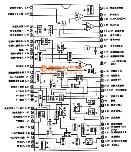
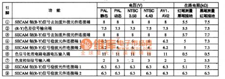
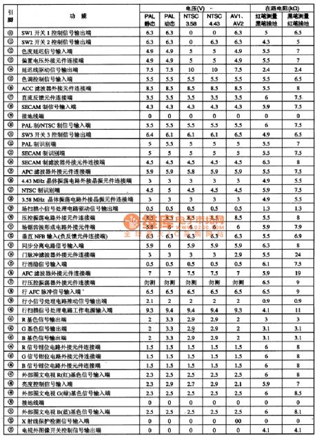
TA875913N brightness, color, line-field scanning circuit
Published:2011/5/6 21:33:00 Author:TaoXi | Keyword: brightness, color, line-field scanning
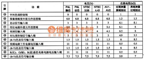
The TA8759BN is designed as one kind of brightness, color, line-field scanning small signal processing integrated circuit, and it can be used in variety brands of domestic and imported large screen color TV.
1.Features
The TA8759BN has the video brightness, chroma signal processing circuit, the line and field scanning small signal processing circuit, the trichromatic signal preprocessing circuit, the PAL/NTSC/SECSM standard switch control circuit, the external Photo circuit signal interface circuit, the X-ray protection circuit, the 3 standards color difference signal preprocessing circuit and other accessibility circuit.
2.Pin functions and data
The TA8759BN is in the 64-pin dual in-line package, the pin functions and data is as shown in table 1.
Table 1 The pin functions and data of the TA8759BN (View)
View full Circuit Diagram | Comments | Reading(1355)
Portable multi-functional battery charger circuit
Published:2011/5/7 12:36:00 Author:John | Keyword: Portable battery charger, multi-functional battery charger
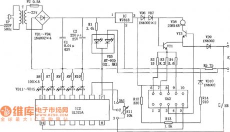
The shown portable multi-functional battery charger circuit is the circuit for a multi-functional Ni-Cd battery charger. It can be used for recharging special nickel-cadmium rechargeable batteries on portable radio transmitters. It can also be used for recharging the standard nickel-cadmium batteries 5, 2 or 4. When the battery capacity reaches saturation during the charging, it automatically terminates the charge, prevents the battery overcharge and has the battery capacity test display. (View)
View full Circuit Diagram | Comments | Reading(2423)
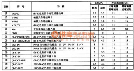
TA8772AN baseband delay line integrated circuit
Published:2011/5/6 9:20:00 Author:TaoXi | Keyword: baseband, delay line
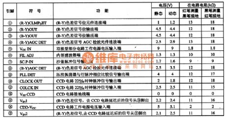
The TA8772AN baseband delay line integrated circuit is produced by the TOSHIBA company that can be used in domestic and imported large screen color TV as the chroma signal delay device.
1.Features
The TA8772AN has the (B-Y), (R-Y) color difference signal delay signal processing circuit, the CCD circuit, the VCO and line pulse phase comparison circuit, the sand castle pulse signal processing circuit, the PAL/NTSC/CECAM three standards switch circuit and other auxiliary circuit.
2.Pin functions and data
The TA8772AN is in the 30-pin DIP package, the pin functions and data is as shown in table 1.
Tips: To determine the TA8772AN's working condition, you can use the oscilloscope to detect the input waveform and output waveform.
Table 1 Pin functions and data of the TA8772AN (View)
View full Circuit Diagram | Comments | Reading(664)
FM / FSK 27MHz transmitter circuit
Published:2011/5/8 3:50:00 Author:John | Keyword: FM / FSK 27MHz transmitter circuit
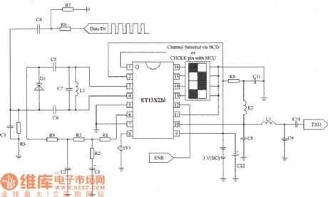
ETl3X220 is a low-cost single-chip transmitter chip which is connected through RF. It can provide 10 communications. And it is suitable for applications of wireless mouse, keyboard and other communication products. The main technical features are as follows: Analog FM or digital FSK modulation mode 5 Channel spacing frequency is about 30 kHz; Supply voltage is 2.3 ~ 3.6 V;Current consumption is 8 mA and low-power mode is 5 μA. (View)
View full Circuit Diagram | Comments | Reading(5056)
Lithium battery fast charging circuit
Published:2011/5/7 12:38:00 Author:John | Keyword: Lithium charger, fast charging circuit
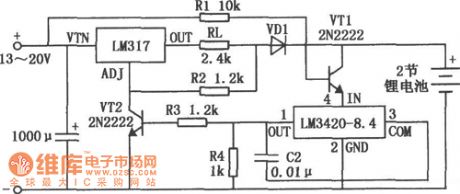
Lithium battery fast charging circuit is shown above. (View)
View full Circuit Diagram | Comments | Reading(1338)
Automatic control circuit for generator starting battery
Published:2011/5/7 12:47:00 Author:John | Keyword: Automatic control circuit, generator, battery
Automatic control circuit for generator starting battery is shown above. (View)
View full Circuit Diagram | Comments | Reading(5662)
| Pages:1933/2234 At 2019211922192319241925192619271928192919301931193219331934193519361937193819391940Under 20 |
Circuit Categories
power supply circuit
Amplifier Circuit
Basic Circuit
LED and Light Circuit
Sensor Circuit
Signal Processing
Electrical Equipment Circuit
Control Circuit
Remote Control Circuit
A/D-D/A Converter Circuit
Audio Circuit
Measuring and Test Circuit
Communication Circuit
Computer-Related Circuit
555 Circuit
Automotive Circuit
Repairing Circuit