
Circuit Diagram
Index 435
Electronic self-locking interlock switch circuit diagram
Published:2011/10/31 3:32:00 Author:May | Keyword: Electronic self-locking interlock switch

Switch's core component is the four operational amplifier LM324, after the ingenious design, each operational amplifier has the twofold function like the voltage comparator and the Schmitt trigger. The voltage applicable scope is wide, and the files may be designed willfully, if it adds a neutral gear, it can be used as the overall reset, when it is used with the digital circuit, they can use the same power source, and the switch's input, output level conforms to digital circuit's connection level, because operational amplifier has high input impedance, the switch's input current is small, it may use the light touching switch. The conductive rubber, thin film switch makes the pressing key. (View)
View full Circuit Diagram | Comments | Reading(2379)
Electronic light touch switch circuit
Published:2011/10/27 21:10:00 Author:May | Keyword: Electronic light touch switch
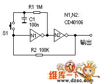
Bistable circuit is a kind of circuit we often use. It is always usedas one-button controlling switchin various circuits.
Working principle: If N1 input end starts in high level, then N2 output also is in high level, then R2 makes the circuit output the high level stably. At this time, because the N1's output port is in low level, therefore C1 discharges by R1. After pressing down S1, N1's input end changes to the low level, the N2's input rises, the N2's output changes to the low level, then the circuit reverses to output the low level stably, and C1 charges by R1. If pressesing S1 again, the circuit returns to another steady state. (View)
View full Circuit Diagram | Comments | Reading(1145)
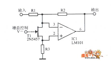
VCA voltage control amplifier circuit diagram
Published:2011/10/18 3:47:00 Author:Ecco | Keyword: VCA , voltage control amplifier
View full Circuit Diagram | Comments | Reading(4726)
The principle diagram of ultrasonic pest repeller
Published:2011/10/18 3:48:00 Author:Ecco | Keyword: Ultrasonic pest repeller
View full Circuit Diagram | Comments | Reading(5045)
The circuit diagram of DKIOOOT OOK315 MHz transmitter
Published:2011/10/18 3:48:00 Author:Ecco | Keyword: MHz transmitter
View full Circuit Diagram | Comments | Reading(809)
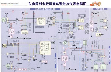
Southeast Delica lightbus warning instrumentation diagram
Published:2011/10/18 3:49:00 Author:Ecco | Keyword: Southeast Delica, lightbus , warning instrumentation
View full Circuit Diagram | Comments | Reading(861)
Eggs hatching incubator 4
Published:2011/10/18 3:45:00 Author:Ecco | Keyword: Eggs hatching incubator
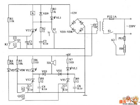
The eggs hatch incubator circuit is composed of the power supply circuit, temperature control circuit and sound and light alarm circuit, and it is shown as the chart. Power supply circuit is composed of the power switch S1, fuse FU2, power transformer T and rectifier diodes VD3 ~ VD6. Temperature control circuit is composed of electric hot thermometer Q1, resistors R1 ~ R3, capacitors C1, C2, thyristor VT1, diode VD9, relay K, light-emitting diode VL1 and manual / automatic switch S2. Sound and light alarm circuit consists of the electric hot thermometer Q2, resistors R4 ~ R9, capacitors C3 ~ C6, thyristors VT2, VT3, diodes VD1, VD2, VD7, VD8, light-emitting diodes VL2, VL3 and buzzer HA.
(View)
View full Circuit Diagram | Comments | Reading(1643)
Eggs hatching incubator 2
Published:2011/10/18 3:45:00 Author:Ecco | Keyword: Eggs hatching incubator
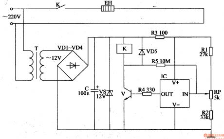
The eggs hatching incubator circuit is composed of the power supply circuit and temperature control circuit, and it is shown in Figure 4-5. Power supply circuit consists of the power transformer T, rectifier diodes VDl-VM, filter capacitor C and zener diode VS. Temperature control circuit consists of the resistors Rl-R5, potentiometer RP, diode VD5, temperature sensor integrated circuit IC, transistor V, Relay K and electric heater EH. Rl-R5 select the 1/4W metal film resistors or carbon film resistors. RP uses the small synthetic membrane potentiometer or multi-turn potentiometer. VDl-VD5 choose 1N4007 silicon rectifier diodes.
(View)
View full Circuit Diagram | Comments | Reading(3127)
555 Refrigerator protector circuit 1
Published:2011/10/18 3:45:00 Author:Ecco | Keyword: 555 , Refrigerator protector
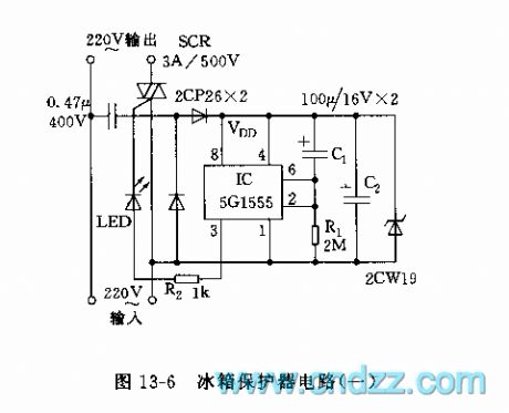
The circuit is shown in Figure 13-6, the circuit is based on 555 circuit to form power delay protection circuit. The connection of C1 makes pin 6 be in high level, and pin 3 be in low level, when the supply is turned again after failure, SCR is cut off. C1 charges, so the pin 2 is lower than the trigger time of 1/3 vdd, that is the delay time td. Icon corresponding td parameter is about 6 minutes. Setting to 555, pin 3 outputs high level. SCR turns on, the refrigerator gets power and the working indicator LED is lit.
(View)
View full Circuit Diagram | Comments | Reading(3446)
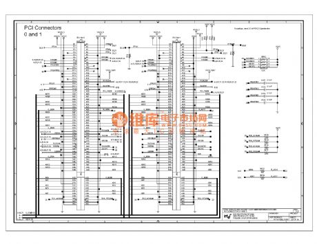
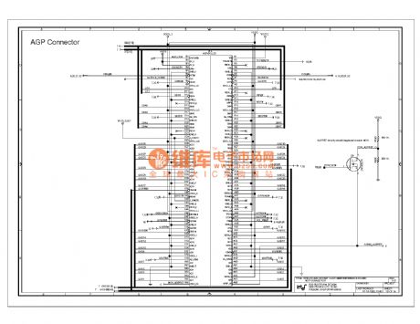
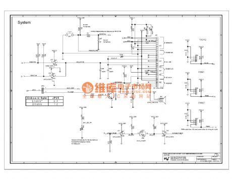
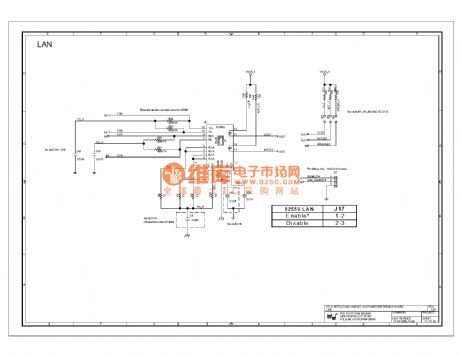
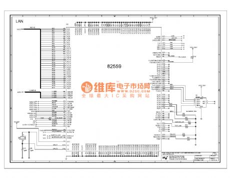
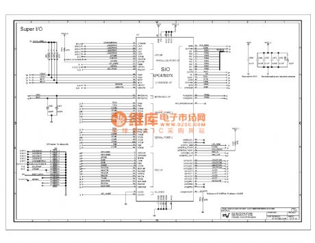
820e computer motherboard circuit diagram 20
Published:2011/10/27 1:47:00 Author:Ecco | Keyword: computer motherboard
View full Circuit Diagram | Comments | Reading(854)
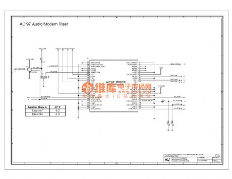
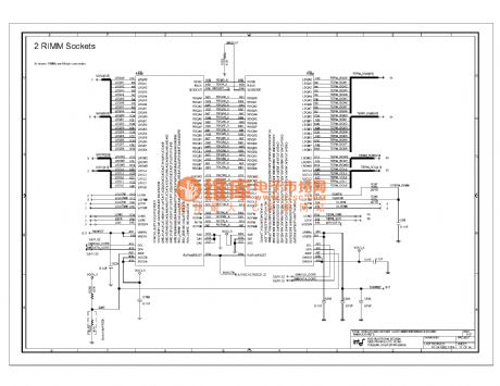
820e computer motherboard circuit diagram 19
Published:2011/10/27 1:46:00 Author:Ecco | Keyword: computer motherboard
View full Circuit Diagram | Comments | Reading(826)
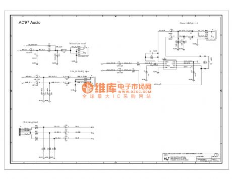
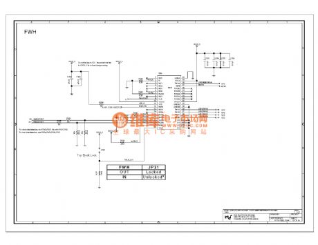
820e computer motherboard circuit diagram 18
Published:2011/10/27 1:45:00 Author:Ecco | Keyword: computer motherboard
View full Circuit Diagram | Comments | Reading(790)
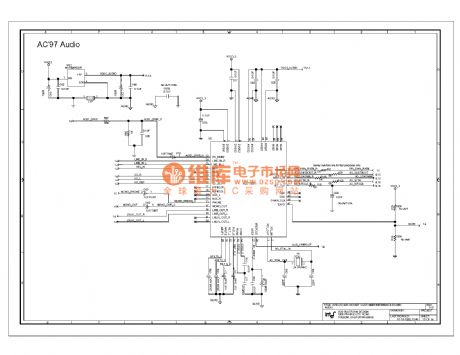
820e computer motherboard circuit diagram 17
Published:2011/10/27 1:45:00 Author:Ecco | Keyword: computer motherboard
View full Circuit Diagram | Comments | Reading(780)
820e computer motherboard circuit diagram 16
Published:2011/10/27 1:44:00 Author:Ecco | Keyword: computer motherboard
View full Circuit Diagram | Comments | Reading(806)
820e computer motherboard circuit diagram 15
Published:2011/10/27 1:44:00 Author:Ecco | Keyword: computer motherboard
View full Circuit Diagram | Comments | Reading(866)
820e computer motherboard circuit diagram 14
Published:2011/10/27 1:43:00 Author:Ecco | Keyword: computer motherboard
View full Circuit Diagram | Comments | Reading(778)
820e computer motherboard circuit diagram 13
Published:2011/10/27 1:43:00 Author:Ecco | Keyword: computer motherboard
View full Circuit Diagram | Comments | Reading(799)
820e computer motherboard circuit diagram 12
Published:2011/10/26 1:52:00 Author:Ecco | Keyword: computer motherboard
View full Circuit Diagram | Comments | Reading(793)
820e computer motherboard circuit diagram 11
Published:2011/10/26 1:52:00 Author:Ecco | Keyword: computer motherboard
View full Circuit Diagram | Comments | Reading(802)
820e computer motherboard circuit diagram 10
Published:2011/10/26 1:51:00 Author:Ecco | Keyword: computer motherboard
View full Circuit Diagram | Comments | Reading(785)
| Pages:435/2234 At 20421422423424425426427428429430431432433434435436437438439440Under 20 |
Circuit Categories
power supply circuit
Amplifier Circuit
Basic Circuit
LED and Light Circuit
Sensor Circuit
Signal Processing
Electrical Equipment Circuit
Control Circuit
Remote Control Circuit
A/D-D/A Converter Circuit
Audio Circuit
Measuring and Test Circuit
Communication Circuit
Computer-Related Circuit
555 Circuit
Automotive Circuit
Repairing Circuit