
Circuit Diagram
Index 438
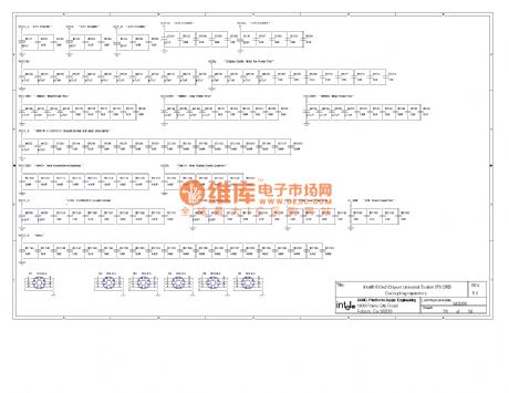
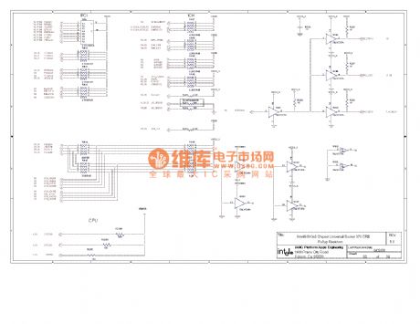
810 computer motherboard circuit diagram 36
Published:2011/10/25 21:33:00 Author:Ecco | Keyword: computer motherboard
View full Circuit Diagram | Comments | Reading(799)
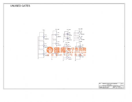
810 computer motherboard circuit diagram 35
Published:2011/10/25 21:36:00 Author:Ecco | Keyword: computer motherboard
View full Circuit Diagram | Comments | Reading(856)
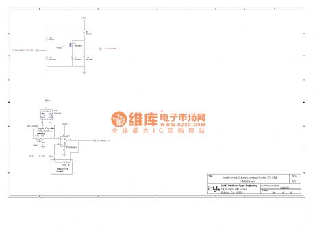
810 computer motherboard circuit diagram 34
Published:2011/10/25 21:36:00 Author:Ecco | Keyword: computer motherboard
View full Circuit Diagram | Comments | Reading(930)
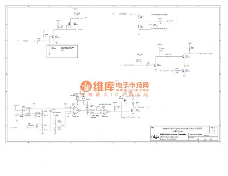
810 computer motherboard circuit diagram 33
Published:2011/10/25 21:35:00 Author:Ecco | Keyword: computer motherboard
View full Circuit Diagram | Comments | Reading(765)
810 computer motherboard circuit diagram 32
Published:2011/10/25 21:34:00 Author:Ecco | Keyword: computer motherboard
View full Circuit Diagram | Comments | Reading(796)
Digital displaying photoelectric counter circuit diagram
Published:2011/9/26 21:50:00 Author:Rebekka | Keyword: Digital displaying , photoelectric counter
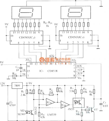
The circuit has optical input circuit (VD, 3DU12), pulse forming circuit (IC1A, IC1B form the voltage comparator; optical coupler; transistor switching circuit) and counting and display circuit. (View)
View full Circuit Diagram | Comments | Reading(2765)
Digital Potentiometers X9511 circuit diagram
Published:2011/9/16 0:50:00 Author:Rebekka | Keyword: Digital Potentiometers
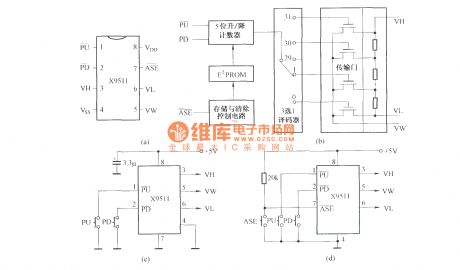
X9511 is a of non-volatile Digital Potentiometer with digital integrated circuit manufacturing process. Its internal binary counter is composed of five binary counter, five-bit rewritten read-only memory (that E2PROM), storage and clear control circuit, thirty-two selected one decoder circuit, transmission gate and resistor arrays and other components. Pin and functionare shown as above. (View)
View full Circuit Diagram | Comments | Reading(1558)
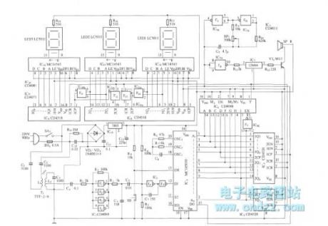
Demodulation decoding and display circuit diagram
Published:2011/9/26 2:22:00 Author:Rebekka | Keyword: Demodulation decoding , display circuit
View full Circuit Diagram | Comments | Reading(759)
The driver circuit diagram of two infrared light-emitting diodes
Published:2011/9/26 2:23:00 Author:Rebekka | Keyword: driver circuit, light-emitting diode
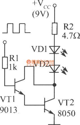
View full Circuit Diagram | Comments | Reading(967)
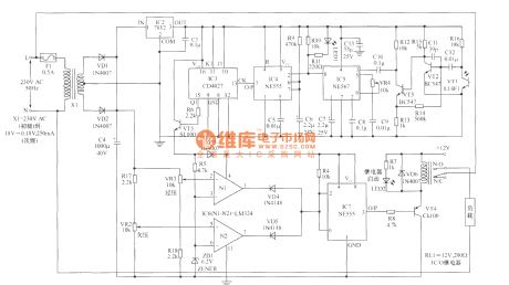
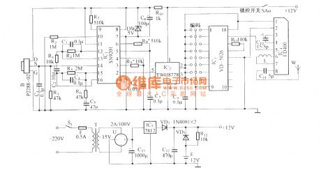
Remote control load protection circuit diaram
Published:2011/9/26 21:55:00 Author:Rebekka | Keyword: Remote control load protection
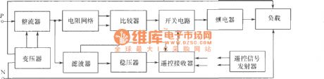

Remote control block diagram of the load protection.
Remote control transmitter.
Remote control receiver and load protection circuits.
Load protection's main functions are: (1) When the power supply voltage is too low or too high, the load will be off automatically; (2) When the power supply voltage is restored, the load power will be connected automatically; (3)Ot provides powerfor normal indication, When the voltage is too low or too high, the light will turn off; (4) Using remote control to remote control power.
(View)
View full Circuit Diagram | Comments | Reading(1345)
Pyroelectric detect fifteenth road alarm system circuit diagram
Published:2011/9/26 2:17:00 Author:Rebekka | Keyword: Pyroelectric detect alarm system
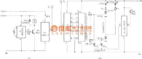
The picture (A) shows the detection and transmission circuit;The picture (B) shows the receiver alarm circuit. (View)
View full Circuit Diagram | Comments | Reading(661)
Pyroelectric infared detection wireless alarm circuit diagram
Published:2011/9/26 22:02:00 Author:Rebekka | Keyword: Pyroelectric infared detection , wireless alarm
View full Circuit Diagram | Comments | Reading(904)
Pyroelectric detection and radio transmitter circuir diagram
Published:2011/9/26 2:15:00 Author:Rebekka | Keyword: Pyroelectric detection , radio transmitter
View full Circuit Diagram | Comments | Reading(783)
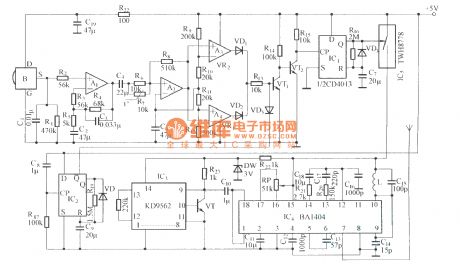
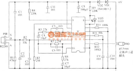
Human infrared thermal release alarm
Published:2011/9/26 22:01:00 Author:Rebekka | Keyword: Human infrared, thermal release alarm

Human infrared thermal release alarm can receive the heat releasing infrared ray issued by the body during the day or night, then it willgive the sound and light alarm. It is ideal for electronic guard. Working principle: The circuit uses imported IC, general-purpose sensor control circuit, high input impedance operational amplifier, it consists of the timer, the timer latch, and the operating voltage is 3.5V ~ 5V, and quiescent currentis 60μA. It uses 3 ~ 4 1.5V batteries or 6V ~ 12V rectifier. Pyroelectric infrared sensor RIP09 TL receives body heat release signal. The signal will be amplified by the first stage op amp in IC. Then it will be amplified and coupled by the second level of C6 amplifier. Then it will be sent to built-in comparator to have bidirectional amplitude discrimination. R2, C2 are delay control. If you need longer hours of work, you can increase the R2's resistance or the capacitance value ofC2, the circuit is set to 3s ~ 4s.
(View)
View full Circuit Diagram | Comments | Reading(2395)
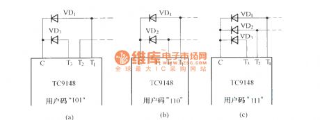
The attachment method of TC9148 user code
Published:2011/9/27 21:13:00 Author:Rebekka | Keyword: attachment method , user code
View full Circuit Diagram | Comments | Reading(794)
BL20106 infrared receiver preamplifier integrated application circuit diagram
Published:2011/9/27 1:59:00 Author:Rebekka | Keyword: infrared receiver preamplifier , integrated circuit
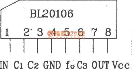

BL20106 is produced by Shanghai Belling Electronic Technology Co., Ltd. It is infrared remote control system for receiving bipolar preamplifier ASIC. Its features are: Low power consumption, low voltage, the internal band-pass filter everywhere; Output is an open collector output, and it can be connected with CMOS and TTL circuit; Input can be directly connected with the photodiode. Domestic and foreign similar products are D20106, CX20106, KA2184A and these can be directly interchangeable.
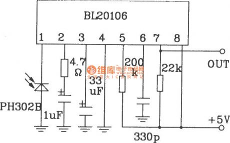
The figure below shows a typical application circuit constituted by the BL20106, andthe circuit is very simple, and its typical operating voltageis 4.7 ~ 5.3V, the circuit operating frequency is F0 = 40kHz
BL20106 shape pin map.
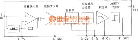
BL20106 internal block diagram.
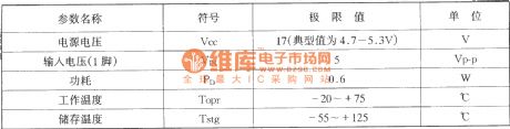
BL20106 limit of the operating parameters: (TA = 25 ℃)
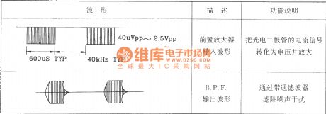
BL20106 working waveform is shown as below:
(View)
View full Circuit Diagram | Comments | Reading(1271)
BA1404 Internal schematic diagram
Published:2011/9/27 1:56:00 Author:Rebekka | Keyword: Internal schematic diagram
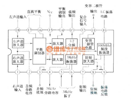
BA1404 IC is a dedicated FM transmitter circuit.
(View)
View full Circuit Diagram | Comments | Reading(1401)
Electronic dog alarm circuit diagram
Published:2011/9/27 21:03:00 Author:Rebekka | Keyword: Electronic dog alarm
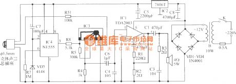
(1)Thepartschematic of infrared sensor electronic dog alarm probe.
Electronic dog alarm is composed of pyroelectric infrared sensor and alarm control speaker.
Alarm controlling speaker's principle diagram. (View)
View full Circuit Diagram | Comments | Reading(1571)
VD5026/27 pinout function circuit diagram
Published:2011/9/27 21:39:00 Author:Rebekka | Keyword: pinout function
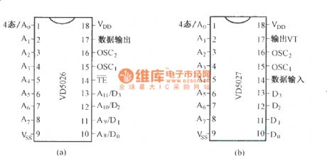
Integrated digital coding circuit VD5026 and its supporting decoding circuit VD5027 are a pair of commonly used digital code, decoding circuit. The pinout function circuit diagram is shown as the chart. (View)
View full Circuit Diagram | Comments | Reading(1125)
YN5101/5201 Multi-channel infrared remote control encoder and decoder typical application circuit diagram
Published:2011/9/27 21:36:00 Author:Rebekka | Keyword: infrared remote control , encoder and decoder, typical application
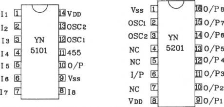
YN5101/5201 encoder / decoder extreme working parameters: Supply voltage is0 ~ 6v; input / output voltage: (Vss-0.2V) / (VDD +0.3 v); maximum power consumptionis 500mW; Operating Temperature is -20 ~ +70 ℃; Storage temperature is-55 ~ +125 ℃.
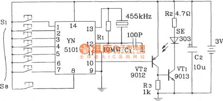
Typical application circuit YN5101 encoding device.
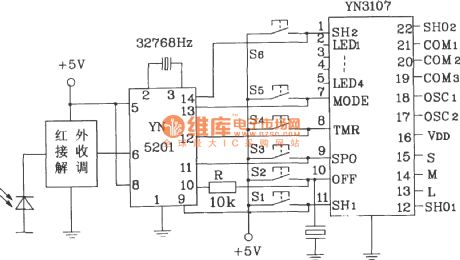
Typical application circuit decoding device YN5201.
Infrared receiver demodulation circuit can use a dedicated infrared modules or infrared preamplifier IC dedicated to form infrared demodulation circuit. The general infrared preamplifier IC models are: CX2106A, μPCI373HA, μPCI490 and KA2184, etc.
(View)
View full Circuit Diagram | Comments | Reading(5309)
| Pages:438/2234 At 20421422423424425426427428429430431432433434435436437438439440Under 20 |
Circuit Categories
power supply circuit
Amplifier Circuit
Basic Circuit
LED and Light Circuit
Sensor Circuit
Signal Processing
Electrical Equipment Circuit
Control Circuit
Remote Control Circuit
A/D-D/A Converter Circuit
Audio Circuit
Measuring and Test Circuit
Communication Circuit
Computer-Related Circuit
555 Circuit
Automotive Circuit
Repairing Circuit