
Circuit Diagram
Index 421
Key pin features of IR3F02 operational amplifier
Published:2011/11/4 3:05:00 Author:Ecco | Keyword: Key pin features , operational amplifier
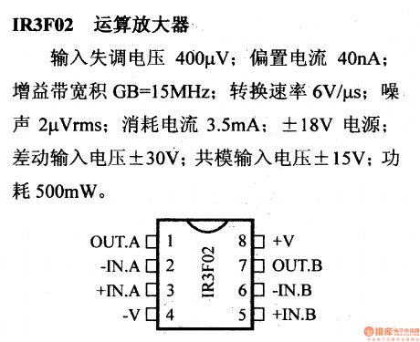
Input offset voltage is 400μV; Bias current is 40nA; Gain-bandwidth product GB=15MHz; Switching rate is 6V/μS; Noise is 2μVms; Current consumption is 3.5mA; it uses ±18V power source; Differential motion input voltage is ±30V; Syntype input voltage is ±15V; Power loss is 500mW.
(View)
View full Circuit Diagram | Comments | Reading(1417)
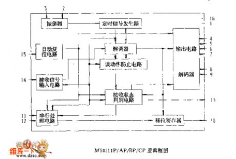
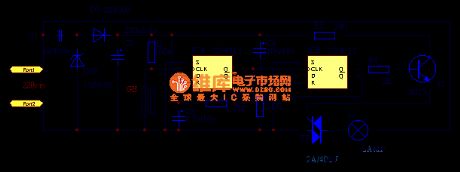
The logic box circuit of M50111P/AP/By/CF
Published:2011/10/18 21:00:00 Author:Ecco | Keyword: logic box
View full Circuit Diagram | Comments | Reading(644)
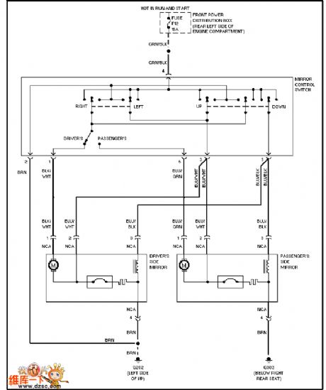
BMW electric rearview mirror circuit diagram
Published:2011/10/18 21:16:00 Author:Ecco | Keyword: BMW , electric rearview mirror
View full Circuit Diagram | Comments | Reading(1742)
Timing control circuit diagram
Published:2011/10/18 21:25:00 Author:Ecco | Keyword: Timing control
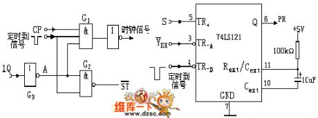
The timing control circuit is key to the design for responder, it should complete the following three functions: ① The host pulls the controlling switch to start position, then the speaker emits sound, the answer circuit and timing circuit will be in normal working condition. ② When the players press the answer key, speaker works, then the answer circuit and timing circuit stop working. ③ When the set answer time is up, no answer in time, the speaker also emits sound, then the answer circuit and timing circuit stop working.
(View)
View full Circuit Diagram | Comments | Reading(978)
BMW starter circuit diagram
Published:2011/10/18 21:28:00 Author:Ecco | Keyword: BMW starter
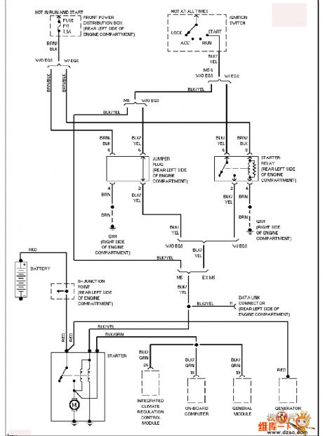
View full Circuit Diagram | Comments | Reading(1104)
BMW wiper and washer circuit
Published:2011/10/18 21:40:00 Author:Ecco | Keyword: BMW , wiper , washer
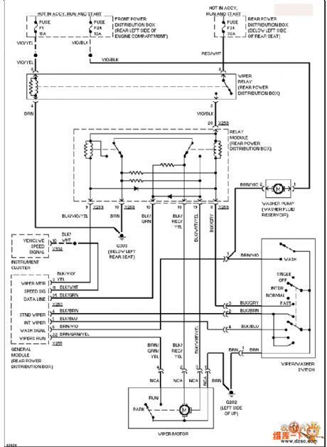
View full Circuit Diagram | Comments | Reading(804)
Electric flute alarm circuit
Published:2011/11/8 21:10:00 Author:Ecco | Keyword: Electric flute alarm, 555
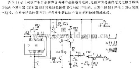
Figure 5.21 shows the tone circuit circuit which can produce two voices with rising tone and dropping tone. Electric flute sound is generated by two generators coupled by optical coupler ( single-junction transistor 2N2648 and the timer 555). 555 generates 0.3HZ frequency signal which makes single-junction transistor VT2 keep this sound increasing or decreasing according to the section.
(View)
View full Circuit Diagram | Comments | Reading(1539)
Motor immersion protection circuit
Published:2011/11/8 21:11:00 Author:Ecco | Keyword: Motor immersion protection
View full Circuit Diagram | Comments | Reading(1200)
The 8019 schematic diagram controlling by 5402
Published:2011/11/8 21:13:00 Author:Ecco | Keyword: schematic diagram
View full Circuit Diagram | Comments | Reading(873)
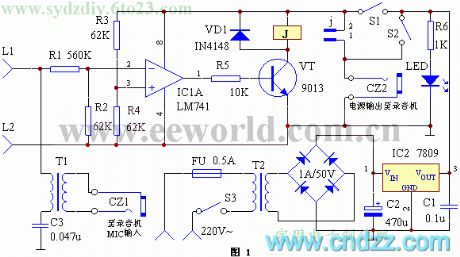
Automatic telephone recording controlling device
Published:2011/11/8 20:33:00 Author:Ecco | Keyword: Automatic, telephone recording , controlling device
View full Circuit Diagram | Comments | Reading(914)
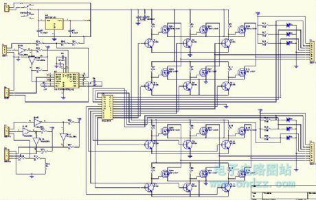
PWM speed regulation circuit for motor
Published:2011/10/19 1:33:00 Author:Ecco | Keyword: PWM speed regulation, motor
View full Circuit Diagram | Comments | Reading(872)
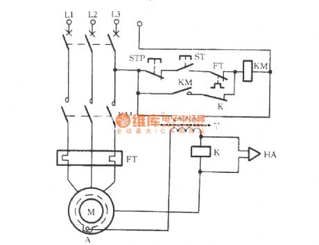
Motor overload protection circuit
Published:2011/11/8 20:32:00 Author:Ecco | Keyword: Motor overload protection
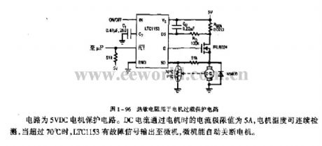
The circuit is the 5VDC motor protection circuit. The current extreme of DC current passing the motor is 5A, and the motor temperature is monitoring continuously, when it is more than 70 ℃, LTC1153 has fault signal sending to the computer, then the computer automatically shut off the machine.
(View)
View full Circuit Diagram | Comments | Reading(1775)
Door controlling switch circuit
Published:2011/10/18 22:07:00 Author:Ecco | Keyword: Door controlling switch
View full Circuit Diagram | Comments | Reading(776)
Doorbell circuit
Published:2011/10/18 22:08:00 Author:Ecco | Keyword: Doorbell
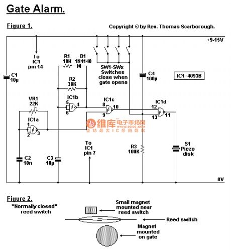
By Rev. Thomas Scarborough Cape Town E-mail scarboro@iafrica.com Figure 1 represents a cheap and simple Gate Alarm, that is intended to run off a small universal AC-DC power supply. IC1a is a fast oscillator, and IC1b a slow oscillator, which are combined through IC1c to emit a high pip-pip-pip warning sound when a gate (or window, etc.) is opened. The circuit is intended not so much to sound like a siren or warning device, but rather to give the impression: You have been noticed. R1 and D1 may be omitted, and the value of R2 perhaps reduced, to make the Gate Alarm sound more like a warning device. VR1 adjusts the frequency of the sound emitted. IC1d is a timer which causes the Gate Alarm to emit some 20 to 30 further pips after the gate has been closed again, before it falls silent, as if to say: I'm more clever than a simple on-off device. Piezo disk S1 may be replaced with a LED if desired, the LED being wired in series with a 1K resistor. Figure 2 shows how an ordinary reed switch may be converted to close (a normally closed switch) when the gate is opened. A continuity tester makes the work easy. Note that many reed switches are delicate, and therefore wires which are soldered to the reed switch should not be flexed at all near the switch. Other types of switches, such as microswitches, may also be used.
(View)
View full Circuit Diagram | Comments | Reading(1288)
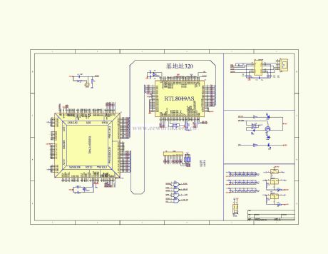
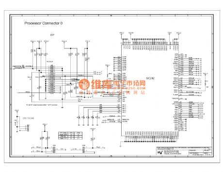
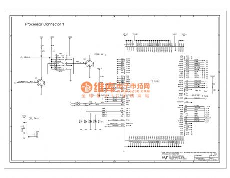
820e computer motherboard circuit diagram 44
Published:2011/10/24 20:12:00 Author:Ecco | Keyword: computer motherboard
View full Circuit Diagram | Comments | Reading(2749)
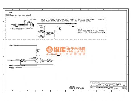
820e computer motherboard circuit diagram 45
Published:2011/10/24 20:03:00 Author:Ecco | Keyword: computer motherboard
View full Circuit Diagram | Comments | Reading(2074)
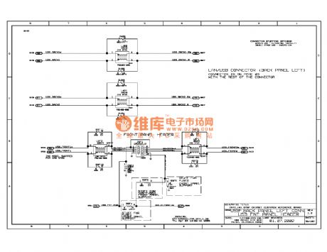
820e computer motherboard circuit diagram 46
Published:2011/10/24 20:03:00 Author:Ecco | Keyword: computer motherboard
View full Circuit Diagram | Comments | Reading(2168)
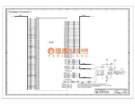
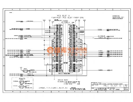
875p computer motherboard circuit diagram 042
Published:2011/10/30 22:55:00 Author:Ecco | Keyword: computer motherboard
View full Circuit Diagram | Comments | Reading(2015)
875p computer motherboard circuit diagram 043
Published:2011/10/30 22:56:00 Author:Ecco | Keyword: computer motherboard
View full Circuit Diagram | Comments | Reading(2172)
875p computer motherboard circuit diagram 044
Published:2011/10/30 22:41:00 Author:Ecco | Keyword: computer motherboard
View full Circuit Diagram | Comments | Reading(2398)
| Pages:421/2234 At 20421422423424425426427428429430431432433434435436437438439440Under 20 |
Circuit Categories
power supply circuit
Amplifier Circuit
Basic Circuit
LED and Light Circuit
Sensor Circuit
Signal Processing
Electrical Equipment Circuit
Control Circuit
Remote Control Circuit
A/D-D/A Converter Circuit
Audio Circuit
Measuring and Test Circuit
Communication Circuit
Computer-Related Circuit
555 Circuit
Automotive Circuit
Repairing Circuit