
Circuit Diagram
Index 441
TWH9238 Self-locking and interlocked hybrid application circuit diagram
Published:2011/10/18 1:54:00 Author:Rebekka | Keyword: Self-locking and interlocked hybrid application
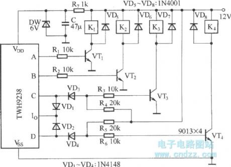
In this circuit, A, B channels are interlocking type output. At the same time, one way plays the controlling role. C, D channels are non-locking output connection, relays K3, K4 use self-locking relays. If it uses a common relay, it should plus a set of connected bistable circuit behind VT3, VT4(or at the output C, D). (View)
View full Circuit Diagram | Comments | Reading(1217)
TWH9238 interlock application circuit diagram
Published:2011/10/18 1:53:00 Author:Rebekka | Keyword: interlock application circuit
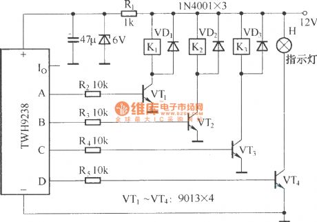
The output terminals A, B, C, D of TWH9238 transmitter pass the transistor drive and drive a DC relay. One output of the circuit plays the role of control at one time. D output connects toan indicator to show shutdown mode. (View)
View full Circuit Diagram | Comments | Reading(1122)
Transmitting and receiving wireless calls ward display circuit (M303S/M303R)
Published:2011/10/18 1:50:00 Author:Rebekka | Keyword: Transmitting and receiving, wireless calls , ward display
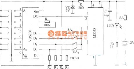
This circuit uses the wireless transmission and digital radio transceiver module M303S/M303R with stable performance, digital decoders VD5026/VD5027. It is stable and reliable to display the call number or room number of beds. It is easy to install. RF transmission power of the circuit is very small. It does not affect the normal operation of medical equipment. Ward Wireless call system is composed of wireless calling transmitter set in ward and radio receiver display set in care duty room. The circuit is shown as below.
Monitors radio receiver circuit is shown as below.
(View)
View full Circuit Diagram | Comments | Reading(2486)
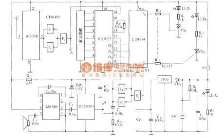
The design of 315M remote control circuit
Published:2011/10/18 1:45:00 Author:Rebekka | Keyword: remote control circuit design
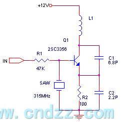
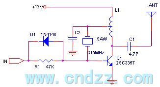

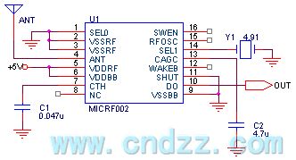
ICRF002 uses ceramic resonators to replacethe different resonator. The receiving frequency can cover 300-440MHz. MICRF002 has two operating modes: scan mode and fixed mode. Scan mode accepts bandwidth of several hundreds of KHz. This mode is mainly used to support the use of LC oscillator transmitter. Because LC transmitting frequencyis higher. In the scan mode, the data communication rate is 2.5K Bytes per second. Bandwidth of fixed pattern is only a few dozens of KHz, and it uses this mode for the supporting of transmitter crystal frequency. Stabilization data rates is up to 10KBytes per second. In addition, the use of wake-up function can wake up decoder or CPU. It can minimize the power consumption. MICRF002 is a complete single-chip superheterodyne receiver circuit. It basically realizes the antenna input after data directly output . Generally the receiver distance is 200 meters. (View)
View full Circuit Diagram | Comments | Reading(2272)
AN5265 audio circuit diagram
Published:2011/10/18 1:40:00 Author:Rebekka | Keyword: audio circuit
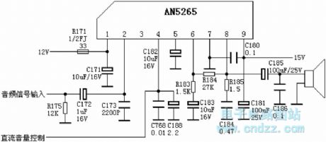
AN5265 pin function and the reference voltage: Pin 1: 12V - Front-level power Pin 2: 5V - audio signal input Pin 3: 0V - mute control terminal (high, quiet) Pin 4: 0.1V - Volume control voltage inputPin 5: 7V - filter-side Pin 6: 7.4V-- negative feedback input Pin 7: 0V -groundPin 8: 7.5V-output end of power amplifierPin 9: 15V - power amplifier class (View)
View full Circuit Diagram | Comments | Reading(14436)
The circuit composed of CSJ-T300A/CSJ-R02A and SCM
Published:2011/9/16 1:15:00 Author:Rebekka | Keyword: SCM
CSJ-T300A and CSJ-R02Aare miniature ultra-long range wireless remote control / data transfer components. CSJ-T300A is transmitter module without the launch code components. The internal circuit is composed of table resonator oscillator, buffer promoting stage, high-frequency power amplifier and amplitude shift keying (ASK) modulator. CSJ-R02A is the SAW frequency stabilized superheterodyne receiver module. The core component of the internal circuit is RX3310A monolithic superheterodyne receiver circuit. If it is matching with the SAW resonator with the frequency stabilized bylocal oscillator. Work is very stable and reliable. The inductor connection is set for SCM system to suppress the received interference. (View)
View full Circuit Diagram | Comments | Reading(762)
Infrared remote control code decoding circuit composed of ED5026/5027
Published:2011/10/18 1:39:00 Author:Rebekka | Keyword: Infrared remote control, code decoding circuit
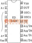
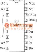
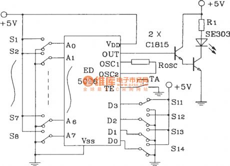
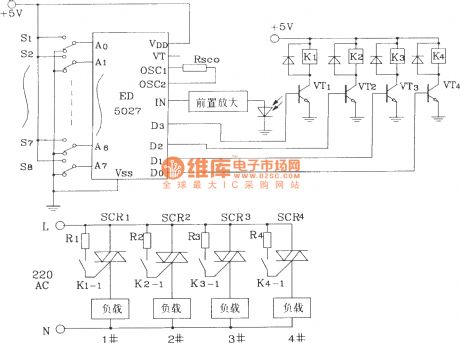
CMOS ED5026/5027 is a type of large-scale digital encoding / decoding ASIC. ED5026 is 8-bit code transmitter (can be extended to 12 bits), and ED5027 is 12-bit information receiving address.They constitute the infrared remote control system. They may also constitutethe radio, ultrasonic remote control mode. Rain gear made extensive application. Similar models are: VK5026/5027,YYH26/YYH27/YHH28 etc.
The following figure shows infrared remote control transmitter / receiver application circuit (remote control four kinds of electrical appliances) composed of ED5026/5027:
(View)
View full Circuit Diagram | Comments | Reading(1384)
DTMF wireless paging system circuit diagram
Published:2011/10/18 1:36:00 Author:Rebekka | Keyword: wireless paging system , DTMF
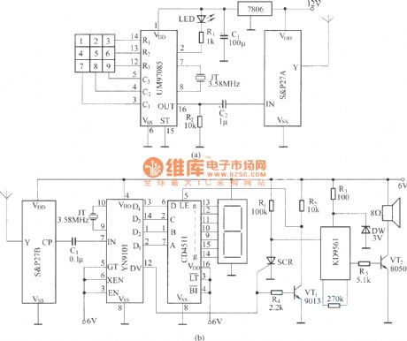
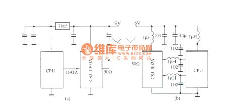
IT usesDTMF encoder output dual tone multi-frequency coded signal to modulate the transmitted carrier frequency. It can form a DTMF encoded radio paging system. The circuit uses DTMF encoding UM97085 and decoding circuit YN9101 circuit to form a small wireless paging system for small internal paging. It is convenient and economical. It is shown in the figure, in which (a) shows the radio transmitting DTMF encoding circuit. Figure (b) shows the radio receiver demodulation, DTMF decoding and reproducing sound signal circuits. (View)
View full Circuit Diagram | Comments | Reading(5289)
The basic radio SR circuit diagram composed of F36-F/J
Published:2011/10/18 1:31:00 Author:Rebekka | Keyword: basic radio SR
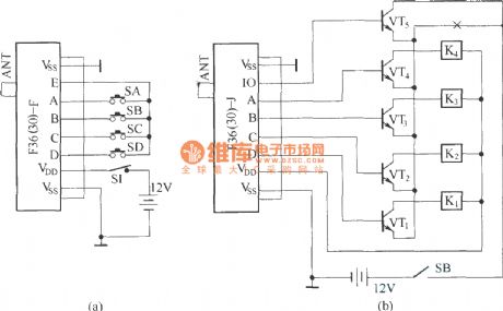
F36-F / J is a pair of digitally encoded radio frequency transceiver components, and the named carrier frequency is 36MHz. F36-F / J components are used in encoding / decoding circuit PT2262/PT2272.
F36-F / J constitutes the basic radio transceiver circuit, whichis shown as above. (View)
View full Circuit Diagram | Comments | Reading(3612)
Automatic exposure controller circuit using ER1211 ASIC
Published:2011/10/20 21:06:00 Author:Rebekka | Keyword: Automatic exposure controller , ASIC
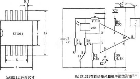
ER1211 is the automatic exposure controlling ASIC in the automatic camera. The pin arrangement is shown in Figure (a), ① is the supply voltage monitoring, ② is the illumination monitoring, ③ is grounding, ④ is illumination warning output, ⑤ is relay driving output, ⑥ is exposure time delay device, ⑦ is exposure delay input, ⑧Automatic focus control, ⑨ is exposure control, ⑩ is power Vcc. If illumination environment light is lower than limit (V2 ≤ V6-0.2V), ④ pin outputs low level, low-light warning light LED emits light. Linkage with the flash K-selector switch is opened at the receiving position A, the corresponding C1 passes W, R1 discharges, the exposure time (discharge time) is fixed, even if the flash automatic metering circuit does not work.
(View)
View full Circuit Diagram | Comments | Reading(775)
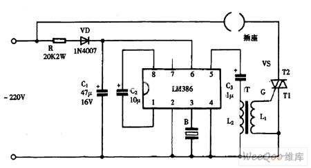
Ventilator auto-control circuit composed of μA555
Published:2011/10/20 20:58:00 Author:Rebekka | Keyword: Ventilator auto-control
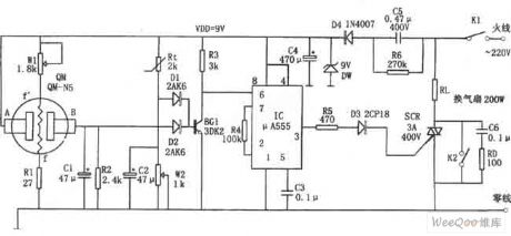
The circuit is composed of the AC step-down rectifier (VDD = +9 V), toxic and hazardous gas sensor head QM-N5, the temperature detection circuit Rt, bistable control circuit. QM-N5 is a gas sensory semiconductor device, Rt uses MF-51 NTC thermistor.
The resistance at the 2 ends of QM between A and B is larger. The potential of B is lower than 1V. It makes the D2, BG2 stop. 555 feet will be reset by the high level of ⑥. The low level output by pin ③ will stop SCR. The ventilation fan does not work.
When the concentrations of indoor harmful gases exceeds the allowable value, the resistance value of QM-N5 will rapidly decrease and the electric potential of B rises, the D2, BG2 will be conducted. (View)
View full Circuit Diagram | Comments | Reading(1631)
C192, 555, CD4028 automatic changing l0-block speed controller circuit
Published:2011/10/20 20:53:00 Author:Rebekka | Keyword: automatic changing, l0-block speed controller, 555
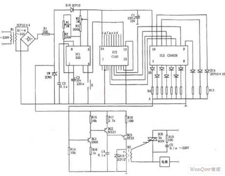
The circuit includes a clock signal generator IC1, counter IC2, decoder IC3, simultaneous phase-shifting circuit (BG1, BG2, BG3), SCR control circuit SCR, buck rectifier circuit. The step-down voltage is stabilized in (9 ~ 10.5) V. It provides power for the entire controller.
The clock signal generator is the multi-vibrator composed of IC1 (555), R2, R3, W1, W2, C3 and other components. The signal frequency depends on the charge and discharge time constant, and adjusting the W1, W2can change the signal frequency and duty cycle. The low-frequency square wave produced by IC1 is count pulse of IC2 and it will be added to the CP side (14 feet). (View)
View full Circuit Diagram | Comments | Reading(2158)
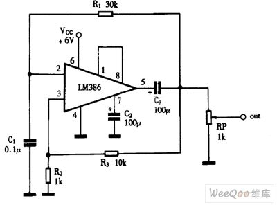
Square-wave generator circuit diagram using LM386
Published:2011/10/20 20:48:00 Author:Rebekka | Keyword: square-wave generator
View full Circuit Diagram | Comments | Reading(2410)
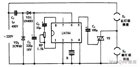
Using LM386 as dual-color music colored lantern controller circuit diagram
Published:2011/10/20 20:43:00 Author:Rebekka | Keyword: dual-color , music colored lantern , controller
View full Circuit Diagram | Comments | Reading(1285)
Using LM386 as low-power positive and negative regulated power supply circuit diagram
Published:2011/10/20 20:42:00 Author:Rebekka | Keyword: low-power, positive , negative , regulated power supply

View full Circuit Diagram | Comments | Reading(1265)
Using LM386 as music colored controller circuit diagram
Published:2011/10/20 20:41:00 Author:Rebekka | Keyword: music color lantern controller
View full Circuit Diagram | Comments | Reading(833)
Chang an Alto Car engine ignition system circuit diagram
Published:2011/10/20 2:32:00 Author:Rebekka | Keyword: Chang an Alto Car , engine ignition system

View full Circuit Diagram | Comments | Reading(1702)
Chang an antelope car air-conditioning system circuit diagram
Published:2011/10/20 2:31:00 Author:Rebekka | Keyword: Chang an antelope , air-conditioning system
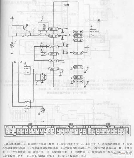
1. Heater motor 2. Electrical load signal isolation diode 3. High and low pressure protection switch 4.A / C switch 5. Evaporator thermistor 6. Engine coolant temperature sensor 7. Condenser fan control relay 8. Condenser the fan motor 9. Compressor and clutch assembly 10. Main relay 11. Controller Ground 12. Heater switch 13. Compressor relay 14. Power Ground A connects to fuse (20A) (IC2), B connects to A / C fuse (15A), C connects to F; fuse (20A), D connects to IG1 fuse (15A)
(View)
View full Circuit Diagram | Comments | Reading(1646)
chang an Antelope car ABS circuit diagram
Published:2011/9/15 22:53:00 Author:Rebekka | Keyword: chang an Antelope , car ABS
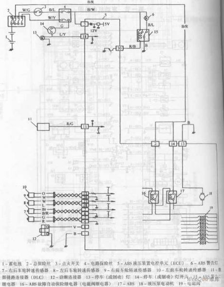
chang'an Antelope car ABS circuit diagram is shown as above.
1. Battery 2. The total fuse 3. Ignition switch 4. 5.ABS fuse circuit hydraulic unit electronic control unit (ECU) 6.ABS warning light 7. The right hand wheel speed sensor 8. Left rear wheel speed sensor 9. The right front wheel speed sensor 10. left front wheel speed sensor 12. diagnostic connector 13. stop (or brake) light 14. stop (or brake) light switch 16.ABS failsafe relay (solenoid valve relay) 17.ABS 18. hydraulic pump motor 19. solenoid valve (View)
View full Circuit Diagram | Comments | Reading(1048)
Power-on sequence control switch (Load control module) circuit using LCE
Published:2011/10/20 22:24:00 Author:Rebekka | Keyword: Power-on sequence , control switch , Load control module, LCE
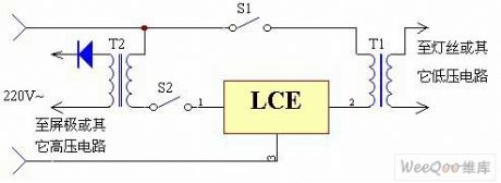
In some electronic device or some other device formed by the tubes, for several supply voltages, such as high pressure and low pressure should beturned on according to a certain order to start the low voltage. You may make a mistake if you are negligent. The use of LCE module can solve the problem. T1 is a low voltage transformer, its primary winding in series isin the LCE's ② feet; T2 is a high-voltage transformer, ofwhich the primary coil in series is in the LCE of ① feet. Normal start sequence should be: First pressing the switch S1, after a while, the vacuum tube filament ispreheating, and then pressing the switch S2. If the operation is in a reverse order, pressing the switch S2 make the circuit stop work, so you can ensure that procedures are correct. (View)
View full Circuit Diagram | Comments | Reading(922)
| Pages:441/2234 At 20441442443444445446447448449450451452453454455456457458459460Under 20 |
Circuit Categories
power supply circuit
Amplifier Circuit
Basic Circuit
LED and Light Circuit
Sensor Circuit
Signal Processing
Electrical Equipment Circuit
Control Circuit
Remote Control Circuit
A/D-D/A Converter Circuit
Audio Circuit
Measuring and Test Circuit
Communication Circuit
Computer-Related Circuit
555 Circuit
Automotive Circuit
Repairing Circuit