
Circuit Diagram
Index 454
Chang an Alto car fuse and relay circuit diagram
Published:2011/10/18 2:54:00 Author:Rebekka | Keyword: Chang an Alto car , fuse and relay
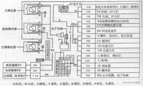
R-red, W-white, C-green, Y-yellow, U-blue, B-black, N-brown, S-gray, R-purple.
Chang'an Alto car fuse and relay circuit diagram is shown as above. (View)
View full Circuit Diagram | Comments | Reading(1355)
Pulse phone 160168 controller circuit diagram
Published:2011/10/18 3:28:00 Author:Rebekka | Keyword: Pulse phone , controller
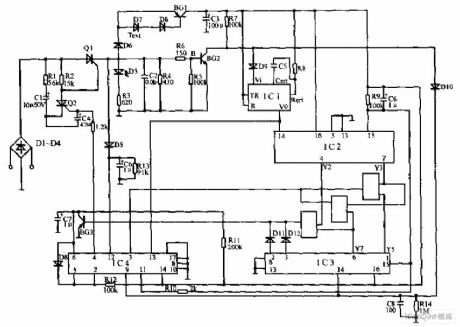
Pulse telephone 160 168 controller circuit is shown as above, the controller can be installed on the phone or on the switchboard of the trunk. It can effectively prevent the others to freely dail 160, 168. D1 ~ D4 use 1N4004, the rest diode use 1N4008. Q1, Q2 use BT169D; BG1 uses 5401, BG2 uses 9014; Resistor uses 0.125W metal resistor; IC1 is CC4098. IC2, IC3choose CD4017. IC4 is CD4066. The controller is connected in series with the phone between the city telephone line and the telephone line. (View)
View full Circuit Diagram | Comments | Reading(1808)
PC infrared remote control receiver circuit diagram
Published:2011/10/18 3:29:00 Author:Rebekka | Keyword: PC , infrared remote, control receiver
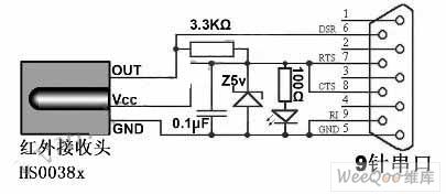
The circuit only has six components. It can remove the light-emitting diode (power indicator) and the 100Ω resistor in order to further simplify the circuit protection. Main components are HS0038A infrared remote control receiver, 5V regulator (1/4W), light emitting diodes, 9-pin serial connector, resistors (3.3KΩ and 100Ω each), electrolytic capacitors (0.1μF, 10V), universal printed circuit plate, wires (at least 3 core) and the battery box (as housing). The total costs no more than 10 yuan. (View)
View full Circuit Diagram | Comments | Reading(2689)
AC switch circuit diagram using optical controlling
Published:2011/10/18 3:31:00 Author:Rebekka | Keyword: optical control , AC switch
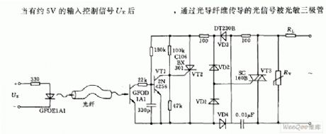
When it has 5V input control signal UE,optical signals pass optical fiber transmission. (View)
View full Circuit Diagram | Comments | Reading(1577)
Video multiplexor circuit diagram
Published:2011/9/13 2:53:00 Author:Rebekka | Keyword: Video multiplexor
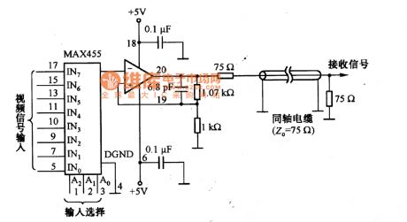
Figure shows a video signal multiplexer, which uses the video amplifier MAX455 with a switch. MAX455 is an integrated chip which includes high isolation analog switch and video frequency amplifier. The frequency of MAX455 is 4MHz, the disconnected isolation of the switch off can achieve 55dB. (View)
View full Circuit Diagram | Comments | Reading(3947)
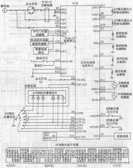
Accord automatic transmission PMC connector pin location and schematic
Published:2011/9/13 2:58:00 Author:Rebekka | Keyword: Accord automatic transmission, PMC connector pin location
View full Circuit Diagram | Comments | Reading(687)
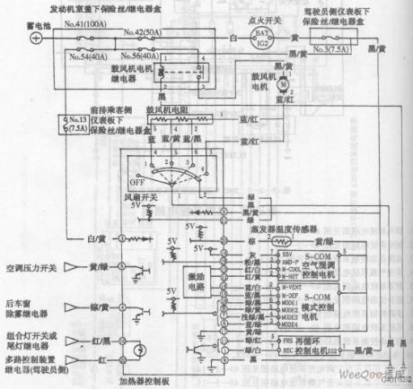
Accord sedan heating system circuit diagram
Published:2011/9/15 22:49:00 Author:Rebekka | Keyword: Accord sedan, heating system
View full Circuit Diagram | Comments | Reading(535)
Four-channel switch circuit diagram
Published:2011/10/18 3:25:00 Author:Rebekka | Keyword: Four-channel switch
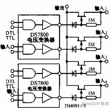
Four-channel switch circuitis shown as the chart, 2N4091 Junction FET power gives each group less than 30Ω on-resistance and a small turn-off leakage current. DS7800 voltage converter provides 10 ~ 20V gate drive voltage to junction field effect transistor, and it is compatible with DTL and TTL circuits. (View)
View full Circuit Diagram | Comments | Reading(1187)
The eight-way remote control circuit diagram composed of module
Published:2011/9/26 21:47:00 Author:Rebekka | Keyword: eight-way remote control , module
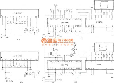
(A) is an eight-way signal remote control selection circuit composed of ZHJ-9904 ; (B) is remote control transmitter circuit; (C) is the eight-way switch control circuit; (D) is remote control transmitter. (View)
View full Circuit Diagram | Comments | Reading(1871)
Interruptible infrared control circuit diagram
Published:2011/9/26 21:48:00 Author:Rebekka | Keyword: Interruptible infrared control
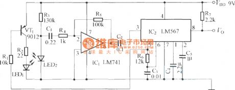
LM567 is a PLL audio decoding circuit.
(View)
View full Circuit Diagram | Comments | Reading(1175)
Infrared sensor automatic sprinkler control circuit diagram using BISS0001
Published:2011/9/26 21:25:00 Author:Rebekka | Keyword: Infrared sensor, automatic sprinkler control
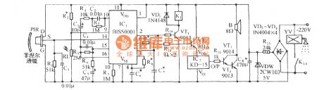
It includes the head of pyroelectric infrared sensor, infrared sensor application specific integrated circuit and the light control circuit composed of external components, and relay control circuit, music voice circui and AC rectifier buck circuit. When there is pedestrian access to the detection area of pyroelectric infrared sensor (PIR). PIR detects the infrared signal radiated by human body. The signal will be converted to low frequency (0.5 ~ 9Hz) signals. The signal will be added to the input op amp (14 feet) of BISS0001. The signal is amplified, filtered and information processed. Then the signal at output terminal 2 feet output a certain delay of the high output control signals. Add the control signal to VT1 relay control circuit to pull in the K1, and its contacts K1-1 closes, the electromagnetic valve W gets water sprays. (View)
View full Circuit Diagram | Comments | Reading(4094)
Transmitter and receiver circuit composed of BTH-801F/801J infrared remote control transmitter and receiver module
Published:2011/9/26 1:44:00 Author:Rebekka | Keyword: Receiver module, infrared remote control transmitter , transmitter and receiver
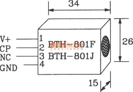
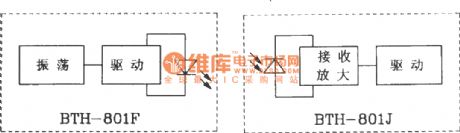
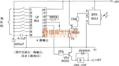
BTH-801F/BTH-80J is a dedicated module for new infrared remote control transmitter and receiver. It is suitable for infrared remote control switch and alarm ect.
BTH-801F/BTH-80lJ shape pinout.
Main electrical parameters of BTH-801F/801J infrared remote control transmitter and receiver module is shown as below. Power supply voltage 4~8V; Receiver module is less than 3mA; Operating frequency is adjustable between 40kHz to 3060kHz; Operating temperature 18~+60℃, storage temperature 25~+90℃; Distance 5~lOm; Mode of action is direct, reflecting both.
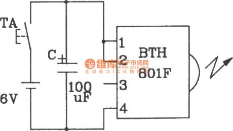
Composed of BIH-801F single infrared remote control transmitter circuit.
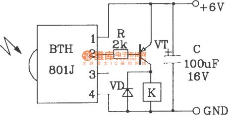
Composed of BTH-801J single infrared remote control transmitter circuit.
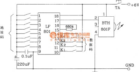
Composed of BTH-801F multi-channel infrared remote control transmitter circuit.
Composed of BTH-801J multi-channel infrared remote control transmitter circuit.
(View)
View full Circuit Diagram | Comments | Reading(1798)
Voltage follower application example circuit diagram
Published:2011/9/13 2:46:00 Author:Rebekka | Keyword: Voltage follower
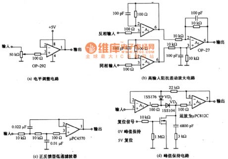
The gain of voltage follower is 0dB. The voltage follower isthe same-phase amplifier circuit. The input impedance in DC range is very high. It is GΩ magnitude. When it has a low utput impedance and ithas μΩ magnitude. It is mainly used as a impedance converter for low-frequency circuit. Figure a, b, c, d are the voltage follower application examples, all these circuits use the features of voltage follower with high input impedance low output impedance. In addition, it is not suitable to use voltage follower. It usually uses inverting amplifier phase amplifier circuit. (View)
View full Circuit Diagram | Comments | Reading(1554)
Toyota Land Cruiser 70 light off-road vehicle interior lights and signal principle circuit diagram
Published:2011/9/13 2:45:00 Author:Rebekka | Keyword: Toyota Land Cruiser 70 , light off-road vehicle
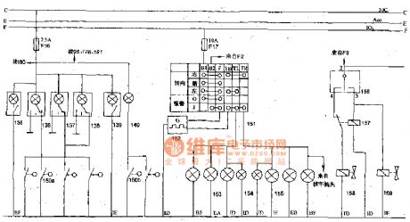
135,139- crew lights(movable vehicle roof in moon shape); 136,137,138- front interior lights; 140-gate controlledlight; 150a, 150b- door control switches; 151-turning and hazard warning switch; 152-turning flasher; 153-left turn signals; 154-turning indicator; 155 right-turn signal; 156-transfer case controlingrelay switch; 157-sub-actuator control relay; 158-transfer case controlingl solenoid valve (2WD); 159-transfer case controlling solenoid valve (4WD); 160-differential lock indicator light. (View)
View full Circuit Diagram | Comments | Reading(2041)
Inversion sampling and maintaining circuit diagram
Published:2011/9/13 2:35:00 Author:Rebekka | Keyword: Inversion sampling , maintaining
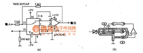
Figure (a) is the inversion sampling and maintaining circuit diagram. When it is maintaining, the op amp's inverting input is in high impedance. The potential of this part is 0. It uses the potential as the protection ring. The circui is shown in figure (b). (View)
View full Circuit Diagram | Comments | Reading(961)
Emitter follower circuit composed of transistors and op-amp combination
Published:2011/9/13 2:32:00 Author:Rebekka | Keyword: Transistors , op-amp combination, Emitter follower
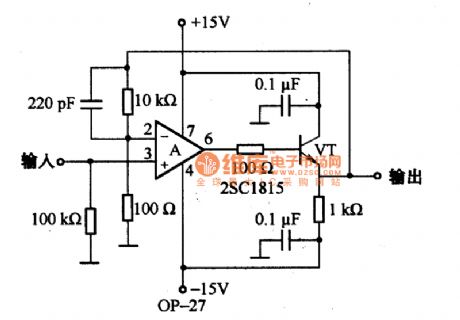
As shown in the diagram, itis the emitter follower composed of transistors and op-amp combinations. For its stability, it needs to access to the bypass capacitor and the series resistor. (View)
View full Circuit Diagram | Comments | Reading(2989)
TDA2611AQ audio power amplifier IC circuit diagram
Published:2011/9/13 2:29:00 Author:Rebekka | Keyword: audio power amplifier , IC
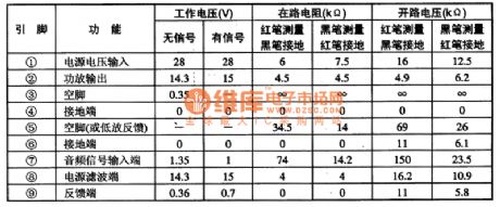
TDA2611AQ is an audio power amplifier integrated circuit produced by Philips of the Netherlands, It is widely used in video, audio, computer audio systems as audio power amplifier. The integrated circuit TDA2611AQ contains audio power amplifier IC circuits, overheating and output short-circuit protection circuit. The connected elements R, C between (5) and (9) feet can increase the input impedance. The IC uses separate 9-pin package, its integrated circuit pin functions and data are listed in Table. (View)
View full Circuit Diagram | Comments | Reading(1483)
TD6301I(2)C bus control display drive IC diagram
Published:2011/9/13 2:28:00 Author:Rebekka | Keyword: bus control display drive
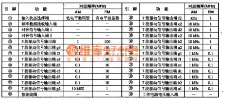
TD6301 is an I (2) C bus control display drive integrated circuit. It is widely used in low-voltage high-grade players and other audio equipment, car audio. TD6301 IC contains 3 groups of 7-segment display drive circuits and the input state selection circuit. The IC uses 28-pin plastic dual in-line structure, the IC 5 pin functions and data arelisted in Table 2. The pin functions and data of TD630lAP IC are shown in table.
(View)
View full Circuit Diagram | Comments | Reading(720)
SA9615 FSK Decoding IC diagram
Published:2011/9/13 2:28:00 Author:Rebekka | Keyword: FSK Decoding
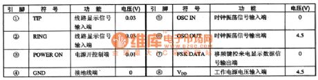
SA9615 is a shift frequency keying decoder integrated circuit. It is widely used for receiving, displaying the calling number sent by switching equipment and information products(such as caller ID cordless, corded telephones, etc.).1. Pin functions and data.SA9615 integrated circuit uses 8-pin dual package structure, the pin functions and data of the integrated circuit are listed in table 1.2. Signal flow.The main signal inputs from ①, ② pin. The demodulated information outputs from pin ⑦ in serial. It will be sent to single-chip microcomputer. And it will be dealed by microcomputer and sent to the desplay. The information will be stored at the same time. (View)
View full Circuit Diagram | Comments | Reading(1663)
Beijing Cherokee BJ2021 light off-road vehicles lighting signal headlamp circuit diagram
Published:2011/9/13 2:26:00 Author:Rebekka | Keyword: Beijing Cherokee , light off-road vehicles
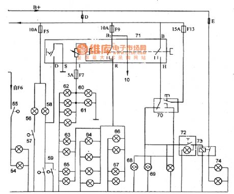
10-buzzer; 54-brake light; 55-brake light switch; 56-glove box lighting; 57-glove box light switch; 58-internal dome lamp; 59-control switch; 60-floor (min drive) lights; 61-air-conditioned light; 62-instrument light; 63-rear width lamp; 64-taillight; 65-frontwidth light; 66-stop light; 67-license plate light; 68-beam light; 69-headlamp; 70-changing light and ultra-light switch; 71-light switch; 72- fog lamp switch; 73-fog lamp relay; 74-fog lamp
(View)
View full Circuit Diagram | Comments | Reading(988)
| Pages:454/2234 At 20441442443444445446447448449450451452453454455456457458459460Under 20 |
Circuit Categories
power supply circuit
Amplifier Circuit
Basic Circuit
LED and Light Circuit
Sensor Circuit
Signal Processing
Electrical Equipment Circuit
Control Circuit
Remote Control Circuit
A/D-D/A Converter Circuit
Audio Circuit
Measuring and Test Circuit
Communication Circuit
Computer-Related Circuit
555 Circuit
Automotive Circuit
Repairing Circuit