
Circuit Diagram
Index 445
2-way controller circuit diagram with distinct switch
Published:2011/10/19 22:52:00 Author:Rebekka | Keyword: 2-way controller , distinct switch
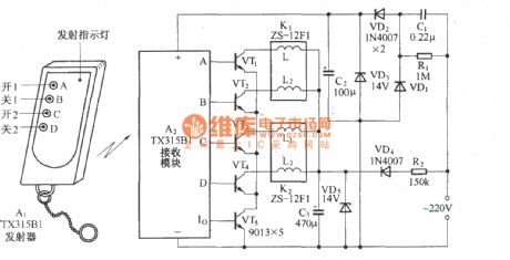
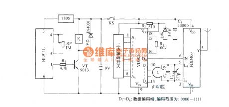
The four remote switching circuit is shown as above. It uses ZS-01F memory self-locking type bistable relay, so the remote control receiver circuit in the circuit output pulse signal will open the related control functions. However, the circuit also exists such a problem: As the control circuit's on and offbuttons usesthe same remote transmitter button, sometimes due to the phenomenon of false positives caused by misuse, this circuit is not allowed for some accused appear. This control circuit will switch to another relay in the relay, the remote control transmitter. Respectively, it uses two different keys to control the circuit on and off, so opening and closing control is clear, you can avoid the misuse phenomenon. (View)
View full Circuit Diagram | Comments | Reading(2223)
The doppler effect automatic switching circuit using RD9481
Published:2011/10/19 22:48:00 Author:Rebekka | Keyword: Doppler effect, automatic switching
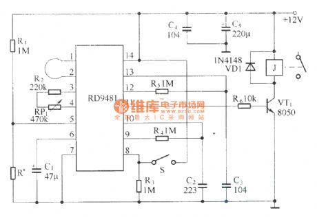
RD9481 is a special hybrid microwave integrated circuit object displacement detection. It can accurately detect moving objects. Its internal circuitryis composed ofthe microwave transceiver circuits. It is composed of two gated amplifiers, voltage comparator, state controller, the delay timer, blocked the timer and reference voltage source. (View)
View full Circuit Diagram | Comments | Reading(1521)
Wireless track warning module with wide frequency rolling code ( KB318/KB318R )
Published:2011/10/19 22:45:00 Author:Rebekka | Keyword: Wireless track , warning module , wide frequency, rolling code
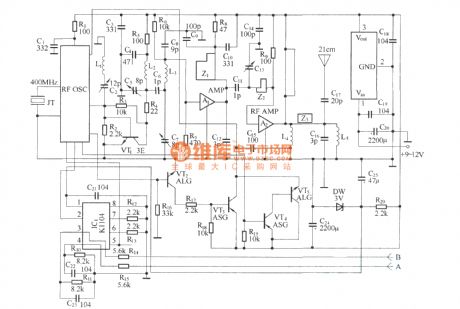
Remote control transmitter schematic.
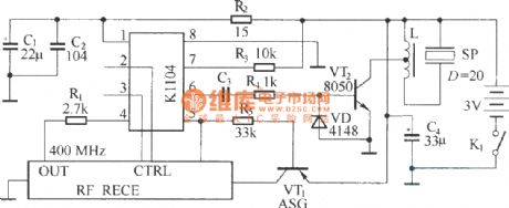
Micro receiver circuit.
The circuitsare used for automobiles, motorcycles and other alarm feedback occasions that needs long-distance wireless BP machine-style. It adopts advanced technologies and devices with improved functionality. It is better than other similar products.It iscomposed of a wireless transmitter KB318T (or KB923T) and a key ring type micro receiver alarm KB318R (or KB923R).
(View)
View full Circuit Diagram | Comments | Reading(863)
Pyroelectric detection wireless security system circuit diagram
Published:2011/10/20 2:08:00 Author:Rebekka | Keyword: Pyroelectric detection, wireless security system
Pyroelectric detection wireless transmitter circuit.
Pyroelectric detection wireless reciever circuit.
Pyroelectric detection wireless system is composedof the pyroelectric infrared detecting circuit, digital encoding radio transmitter circuit, wireless receiver demodulation circuit, the address decoding circuit and alarm trigger and the voice circuit. HN911 is a new pyroelectric infrared detector module. The features are: low power consumption, good interference immunity (especially anti-electromagnetic interference).
(View)
View full Circuit Diagram | Comments | Reading(2213)
Anti-theft wireless warning circuit diagram
Published:2011/10/20 2:05:00 Author:Rebekka | Keyword: Anti-theft wireless warning
Circuit is shown as above. It is composedof radio frequency (FM) radio transmitter and receiver circuit. When someone broke into the house, the wireless transmitters send FM signals and make the sound of breaking glass. You can listen itaway fromhundred meters, then the power amplifier drives speaker Bto emit sound.
(View)
View full Circuit Diagram | Comments | Reading(1279)
Model ship and car controller circuit diagram
Published:2011/10/20 1:59:00 Author:Rebekka | Keyword: Model ship and car controller
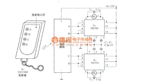
NE556 is a dual time base IC, whichcontains two separate 555 circuits. Each 555 circuit forms a Schmitt trigger. The flipping of trigger is achieved by TX315B1 output control. When the Schmitt trigger input is low, its output terminal outputs high level; When the input is high, its output terminal outputs low level. When the both ends of the motor are high or low level, the motor stops; When the motor is high at one end, the other end is low, the motor rotates; If the ends are high and low swap, then The direction of motor rotation is opposite. (View)
View full Circuit Diagram | Comments | Reading(2451)
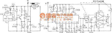
Decorative pendant lamp remote control circuit diagram
Published:2011/10/20 20:40:00 Author:Rebekka | Keyword: Decorative pendant lamp , remote control
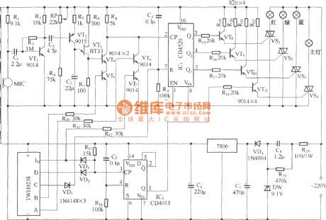
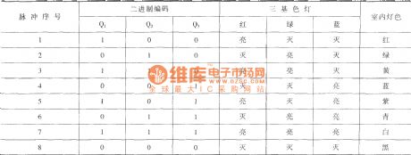
The decorative lamp control circuit is composed by the main light and white color combination of the three-color light. The main light uses 100W high-power incandescent, three-color light for decoration. It uses 30-60W lights. It can use wireless remote controlling. It can use indoor relaxing music to achieve sound control. Discoloration state has seven colors. The circuit is composedof the primary light control circuit, loop color light control circuit, radio circuit and voice-activated remote control color circuit. The output mode of Q1-q3 and the relationship between the color combination of light is shown as above.
(View)
View full Circuit Diagram | Comments | Reading(1779)
Anti-lost children warning circuit diagram(transceiver module composed of RCMlA / RCMlB)
Published:2011/10/20 2:30:00 Author:Rebekka | Keyword: Anti-lost children
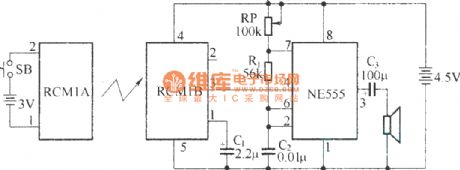
The circuit is composed of the transmitter and receiver, and the core componentsare RCM1A and RCM1B. (View)
View full Circuit Diagram | Comments | Reading(1692)
Toy car circuit controlled by TV remote controller
Published:2011/10/20 21:47:00 Author:Rebekka | Keyword: TV remote controller , toy car circuit
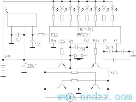
P10 ~ P17 are connected to LED for 8 gear speed display; P3.5, P3.7 control the motor's moving, andthe advance and retreat can not be inlow level, the output period of the width modulated square wave is 80ms. The power transistor is decided by the motor current. The + , - keys of remote controller control the advance and retreat programs. Volume keys are used for acceleration and deceleration, and the power button is used for parking control. Remote control distance is 10 meters, and required furniture will not be blocked. This circuit is a good power supply polarity switching circuit, and the voltage drops on the power loss is very small, simple and practical. (View)
View full Circuit Diagram | Comments | Reading(2138)
An air-conditioner control circuit
Published:2011/9/28 4:33:00 Author:Rebekka | Keyword: Air-conditioner control
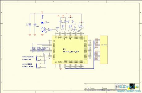
View full Circuit Diagram | Comments | Reading(1036)
Composed of CSJ-T300B and CSJ-R02B remote control circuit diagram
Published:2011/10/20 2:29:00 Author:Rebekka | Keyword: remote control circuit
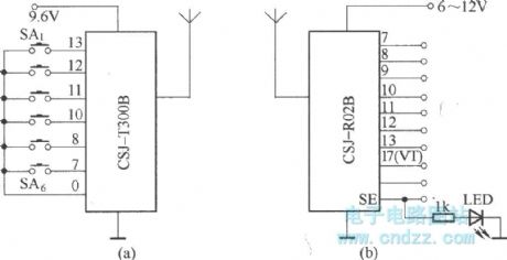
CSJ-T300B/CSJ-R02B is composed of the digital encoding and decoding circuit increasing based on CSJ-T300A/CSJ-R02A. The ontrol circuit is composedof CSJ-T300B and CSJ-R02B. It is shown as the chart. (View)
View full Circuit Diagram | Comments | Reading(2149)
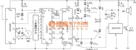
Radio remote control light switch composed of RCM1A/RCM1B
Published:2011/9/28 4:34:00 Author:Rebekka | Keyword: radio remote control light switch
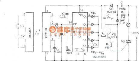
RCM1A/RCM1B is a pair of micro-power FM radio remote control module. The remote control distance is 8-15 meters. The figure shows a radio remote control light switch composedof the module. It consists of transmitter and receiver two parts. Click the emission control buttons, lamp on; Then click the button, lamp off. Transmitter circuit uses RCM1A module and 3V battery-powered; The receiver circuit is composed of the RCM1B, decade counter CD4017 and the thyristor switch circuit. (View)
View full Circuit Diagram | Comments | Reading(1894)
Single and multi-channel remote control transmitter and receiver circuit composed of TDC1808/1809 RF
Published:2011/10/20 2:26:00 Author:Rebekka | Keyword: RF single-and multi-channel , remote control transmitter and receiver
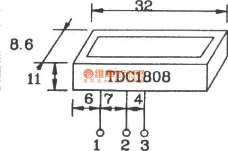
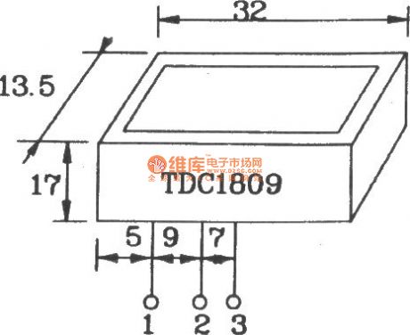

TDC1808/1809 RF wireless transmitter / receiver module-specific can easily form a variety of wireless remote control device.
TDC1808 shape pin map.
TDC1809 shape pin map.
TDC1808/1809 remote control transmitter / receiver module is widely used in a frequency range applications. Transmitter module TDCl808n has been launched in the 250 - 350MHz frequency modulatio at the factory. There are l0 different frequencies available to use. TDCl808 uses A, B two connection methods: No modulation signal or external modulation of various signal transmission. Ssuch as: audio modulation or digital modulation. Therefore, you can connect a variety of modulated signals to form the transmitter circuit. The operating voltage of TDCl808 factory is set at 9V. The plant can also produce l.5 ~ 18V power supply voltage of transmitter modules. The operate voltage of receiver module TDCl809 is 5.1V. If you need a 5Vworking voltage, you can also ask for customized module from the plant.
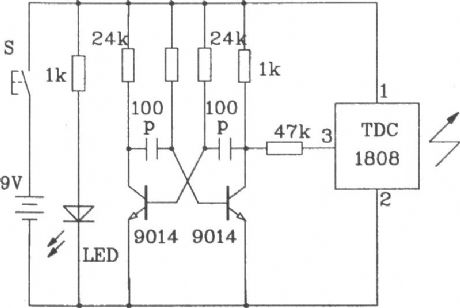
RF channel remote control transmitter circuit composed of TDC.
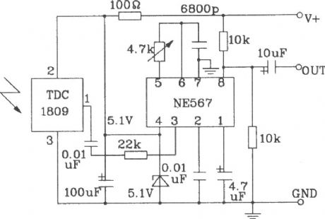
RF channel remote control receiving circuit composed of TDC1809.
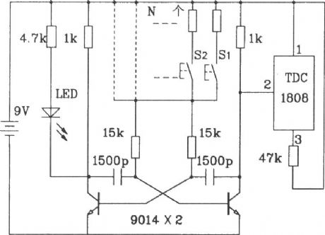
Multi-channel RF remote control transmitter circuit composed of TDC.
Multi-channel RF remote control receiver circuit composed of TDC.
(View)
View full Circuit Diagram | Comments | Reading(3791)
Heterodyne remote control receiving circuit diagram
Published:2011/10/20 2:24:00 Author:Rebekka | Keyword: heterodyne , remote control receiving circuit

TDA5200 is a low-power single-chip ASK superheterodyne receiver circuit. Its operating frequency range has two block. They are 868 ~ 870MHz and 433 ~ 435MHz. The circuit is highly integrated. It has few external components, perfect function. It is a single receiver circuit with excellentperformance. (View)
View full Circuit Diagram | Comments | Reading(3209)
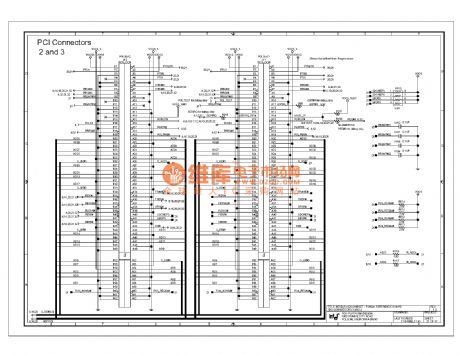
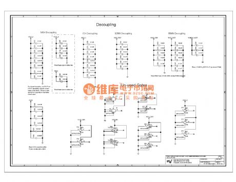
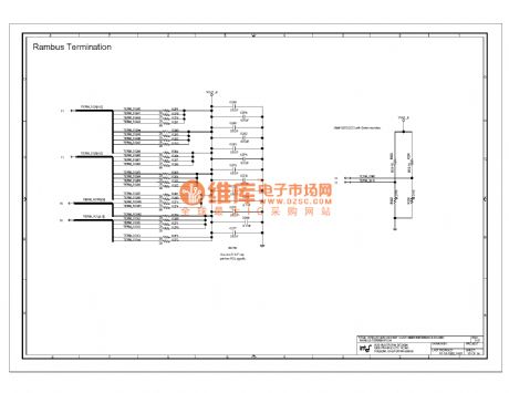
820e computer motherboard circuit diagram 21
Published:2011/10/24 20:33:00 Author:Ecco | Keyword: computer motherboard
View full Circuit Diagram | Comments | Reading(846)
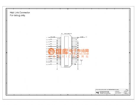
820e computer motherboard circuit diagram 37
Published:2011/10/24 20:29:00 Author:Ecco | Keyword: computer motherboard
View full Circuit Diagram | Comments | Reading(846)
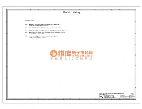
820e computer motherboard circuit diagram 36
Published:2011/10/24 20:28:00 Author:Ecco | Keyword: computer motherboard
View full Circuit Diagram | Comments | Reading(731)
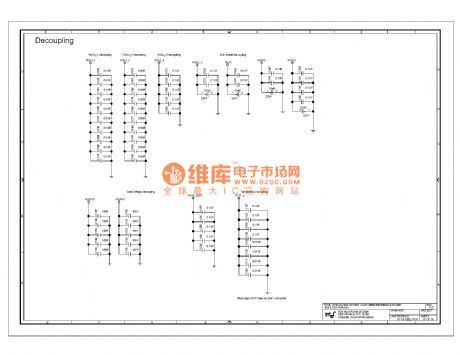
820e computer motherboard circuit diagram 35
Published:2011/10/24 20:27:00 Author:Ecco | Keyword: computer motherboard
View full Circuit Diagram | Comments | Reading(757)
820e computer motherboard circuit diagram 34
Published:2011/10/24 20:26:00 Author:Ecco | Keyword: computer motherboard
View full Circuit Diagram | Comments | Reading(791)
820e computer motherboard circuit diagram 33
Published:2011/10/24 20:26:00 Author:Ecco | Keyword: computer motherboard
View full Circuit Diagram | Comments | Reading(753)
| Pages:445/2234 At 20441442443444445446447448449450451452453454455456457458459460Under 20 |
Circuit Categories
power supply circuit
Amplifier Circuit
Basic Circuit
LED and Light Circuit
Sensor Circuit
Signal Processing
Electrical Equipment Circuit
Control Circuit
Remote Control Circuit
A/D-D/A Converter Circuit
Audio Circuit
Measuring and Test Circuit
Communication Circuit
Computer-Related Circuit
555 Circuit
Automotive Circuit
Repairing Circuit