
Circuit Diagram
Index 449
Hands-free phone chip circuit diagram
Published:2011/10/21 1:56:00 Author:Rebekka | Keyword: Hands-free phone chip
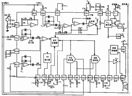
Hands-free phone chip circuit is shown as above, MC3418 chip is widely used in high-quality speakerphone representative blocks and half-duplex voice call. (View)
View full Circuit Diagram | Comments | Reading(2380)
Two-way telephone password device circuit diagram
Published:2011/10/21 2:05:00 Author:Rebekka | Keyword: Two-way telephone password device
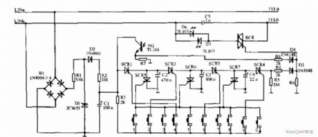
Two-way telephone password device is shown as above, the two-way telephone device is composed of the power circuit, password circuit, * circuit, and self-locking circuit. Password circuit is composed of digital keys 0 to 9, four password set. The figure is set to 4269. The *circuit is composed offour one-way thyristor SCR1 ~ SCR4, three capacitors C2, C3, C4, resistor R4, R5 and diode D3. Self-locking circuit is composed of infrared light emitting diodes D5, D6, infrared receiver, the resistance of transistor BG R7, R8 and diode D4. The 2 ends of LINa, LINb Access an outside line. TELa, TELb pick connect the phone. (View)
View full Circuit Diagram | Comments | Reading(1827)
Low frequency high frequency filter circuit diagram
Published:2011/10/21 2:07:00 Author:Rebekka | Keyword: Low frequency filter, high frequency
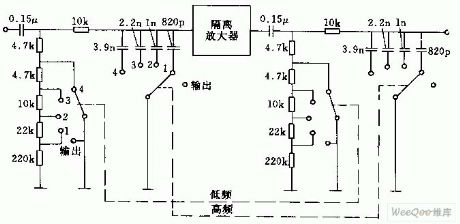
Figure (a) circuit is composed of RC filter with two cascaded parts. It is connected a isolation amplifier between them(such as emitter-follower). Low frequency - high frequency filter adjusts the performance curve by no-load output. It is shown as (b). fu = 40Hz, fu = 11KHz. (View)
View full Circuit Diagram | Comments | Reading(980)
Telephone line anti-theft protection warning device circuit diagram
Published:2011/10/21 2:11:00 Author:Rebekka | Keyword: Telephone line , anti-theft protection , warning device
Call timer circuit is shown as above.
The protective alarm deviceis installedin the user telephone line, when telephone line is stolen,short circuit, open circuit or leakage, thealarm signal will be issued for timely processing. The protective alarm does not need to change the structure and wiring. (View)
View full Circuit Diagram | Comments | Reading(1439)
Hotline automatic dialing devices circuit diagram
Published:2011/10/21 2:13:00 Author:Rebekka | Keyword: Hotline automatic dialing devices
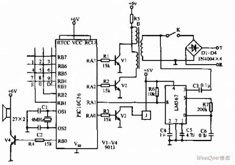
Hotline autodial circuit is shown as below. The automatic dialer uses PIC16C5 Microchip's MCU. This circuit can guaranteethat it can automatically store the last issuing phone number after picking. And it ensures that when it is in the busy tone, it will dial the number automatically over 2 seconds. (View)
View full Circuit Diagram | Comments | Reading(2319)
Bridge driver circuit composed of integrated pressure signal conditioner MAX1450
Published:2011/10/21 1:10:00 Author:Rebekka | Keyword: Bridge driver , integrated , pressure signal , conditioner
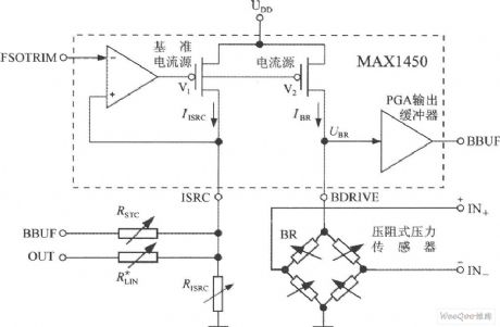
View full Circuit Diagram | Comments | Reading(747)
Sequential timer circuit composed of 556
Published:2011/10/20 22:37:00 Author:Rebekka | Keyword: sequential timer
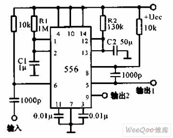
The diagram of sequential timer circuit composed of 556 is shown as above. 556 is a dual timer. The first timer output 1 passes 0.001μF coupling capacitor, then it isadded to the pin 8 of second timer's input end. The total delay is equal to two extension, 1 = 1.1 (R1C1 + R2C2). The wire connected to pin 6 is grounded, then the first timer can be turned on. (View)
View full Circuit Diagram | Comments | Reading(4931)
Two light control relay circuit diagram
Published:2011/10/18 3:25:00 Author:Rebekka | Keyword: Two light control relay
Two light control relay circuit is shown as below. The circuit is a simple light control relay. The relay operating current is 5mA, resistance is2300Ω. The phototransistor sensitivity of the photoelectric conversion is 4μA/ft/cd, if the brightness is 125ft / cd, the relay can work. (A) circuit is the light relay power circuit, (b) circuit is the light relay power circuit. (View)
View full Circuit Diagram | Comments | Reading(1054)
Charging circuit composed of μA741
Published:2011/10/20 22:38:00 Author:Rebekka | Keyword: Charging circuit
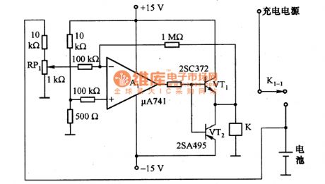
The figure shows the charging circuit composed of μA741. The battery voltage passes RP1 and adds to the inverting input terminal of A1. When the battery voltage is low, A1 outputs high, VT1 and VT2 turn on, the relay K will be energized, then the contacts K1-1 close. The charging power supply charges for the battery. When the battery is fully charged, the voltage is increased, A1 outputs low level, VT1 and VT2 stop, the relay K loses power,then the K1-1 disconnects, the battery will stops charging. (View)
View full Circuit Diagram | Comments | Reading(1679)
Output 15OV/100mA regulator circuit diagram
Published:2011/10/20 22:34:00 Author:Rebekka | Keyword: regulator circuit
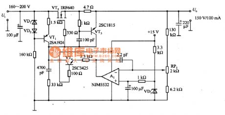
The figure shows the output 150V/100mA regulator circuit. VT3 is the over-current protection circuit, when the output is in short circuit, VT3 protection circuit starts to work. The current in VT2 is controlled at 12OmA. At this time, it adds all the input voltage to the VT2 input voltage drain - source, the production loss is about 2OW. (View)
View full Circuit Diagram | Comments | Reading(1627)
Instrument wiring(with electroniccompass) circuit 2 of Mitsubishi Pajero light off-road vehicle
Published:2011/10/20 22:00:00 Author:Rebekka | Keyword: Mitsubishi Pajero , light off-road vehicle , automobile instrument wiring, electroniccompass
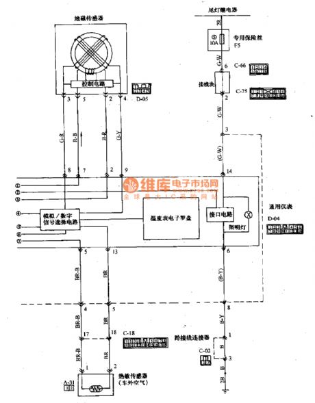
Wiring Color
B: Black LG: light green G: Green L: Blue W: White Y: Yellow SB: sky blue BR; Brown 0: Orange GR: Gray R: red P: Pink V: Purple
(View)
View full Circuit Diagram | Comments | Reading(1001)
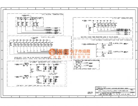
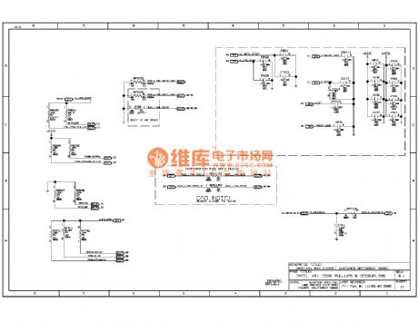
845ddr computer motherboard circuit diagram 07
Published:2011/10/21 2:39:00 Author:Ecco | Keyword: computer motherboard
View full Circuit Diagram | Comments | Reading(810)
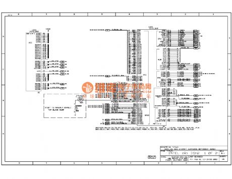
845ddr computer motherboard circuit diagram 06
Published:2011/10/21 2:38:00 Author:Ecco | Keyword: computer motherboard
View full Circuit Diagram | Comments | Reading(862)
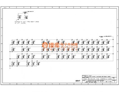
845ddr computer motherboard circuit diagram 05
Published:2011/10/21 2:37:00 Author:Ecco | Keyword: computer motherboard
View full Circuit Diagram | Comments | Reading(913)
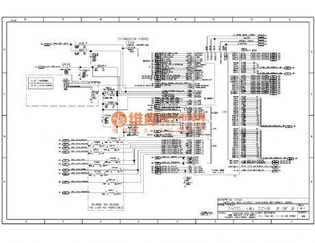
845ddr computer motherboard circuit diagram 08
Published:2011/10/21 2:39:00 Author:Ecco | Keyword: computer motherboard
View full Circuit Diagram | Comments | Reading(835)
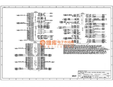
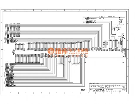
845ddr computer motherboard circuit diagram 22
Published:2011/10/21 2:25:00 Author:Ecco | Keyword: computer motherboard

View full Circuit Diagram | Comments | Reading(770)
845ddr computer motherboard circuit diagram 21
Published:2011/10/21 2:36:00 Author:Ecco | Keyword: computer motherboard
View full Circuit Diagram | Comments | Reading(834)
845ddr computer motherboard circuit diagram 20
Published:2011/10/21 2:35:00 Author:Ecco | Keyword: computer motherboard
View full Circuit Diagram | Comments | Reading(987)
845ddr computer motherboard circuit diagram 19
Published:2011/10/21 2:35:00 Author:Ecco | Keyword: computer motherboard
View full Circuit Diagram | Comments | Reading(943)
845ddr computer motherboard circuit diagram 18
Published:2011/10/21 2:34:00 Author:Ecco | Keyword: computer motherboard
View full Circuit Diagram | Comments | Reading(765)
| Pages:449/2234 At 20441442443444445446447448449450451452453454455456457458459460Under 20 |
Circuit Categories
power supply circuit
Amplifier Circuit
Basic Circuit
LED and Light Circuit
Sensor Circuit
Signal Processing
Electrical Equipment Circuit
Control Circuit
Remote Control Circuit
A/D-D/A Converter Circuit
Audio Circuit
Measuring and Test Circuit
Communication Circuit
Computer-Related Circuit
555 Circuit
Automotive Circuit
Repairing Circuit