
Circuit Diagram
Index 450
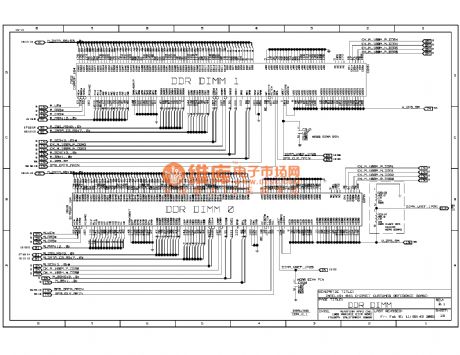
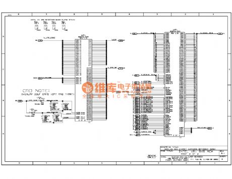
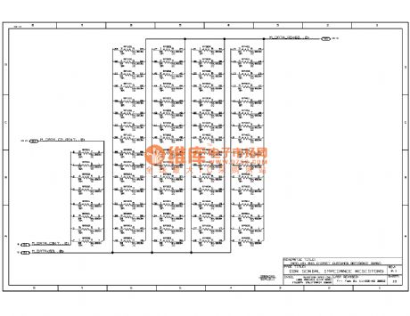
845ddr computer motherboard circuit diagram 15
Published:2011/10/21 2:32:00 Author:Ecco | Keyword: computer motherboard
View full Circuit Diagram | Comments | Reading(827)
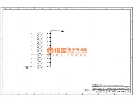
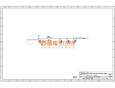
845ddr computer motherboard circuit diagram 14
Published:2011/10/21 2:31:00 Author:Ecco | Keyword: computer motherboard
View full Circuit Diagram | Comments | Reading(793)
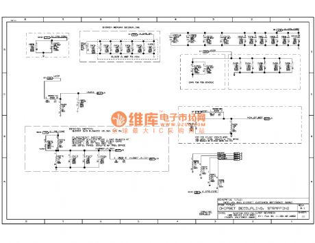
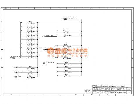
845ddr computer motherboard circuit diagram 12
Published:2011/10/21 2:30:00 Author:Ecco | Keyword: computer motherboard

View full Circuit Diagram | Comments | Reading(1099)
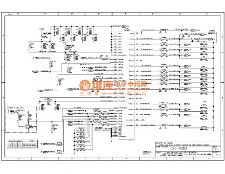
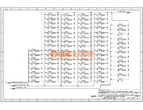
845ddr computer motherboard circuit diagram 11
Published:2011/10/21 2:29:00 Author:Ecco | Keyword: computer motherboard
View full Circuit Diagram | Comments | Reading(922)
845ddr computer motherboard circuit diagram 10
Published:2011/10/21 2:28:00 Author:Ecco | Keyword: computer motherboard
View full Circuit Diagram | Comments | Reading(986)
845ddr computer motherboard circuit diagram 09
Published:2011/10/21 2:40:00 Author:Ecco | Keyword: computer motherboard
View full Circuit Diagram | Comments | Reading(834)
845ddr computer motherboard circuit diagram 44
Published:2011/10/19 2:16:00 Author:Ecco | Keyword: computer motherboard
View full Circuit Diagram | Comments | Reading(839)
845ddr computer motherboard circuit diagram 17
Published:2011/10/21 2:33:00 Author:Ecco | Keyword: computer motherboard
View full Circuit Diagram | Comments | Reading(774)
845ddr computer motherboard circuit diagram 16
Published:2011/10/21 2:33:00 Author:Ecco | Keyword: computer motherboard
View full Circuit Diagram | Comments | Reading(934)
845ddr computer motherboard circuit diagram 13
Published:2011/10/21 2:30:00 Author:Ecco | Keyword: computer motherboard
View full Circuit Diagram | Comments | Reading(791)
SS0001 internal circuit schematic diagram
Published:2011/9/27 21:13:00 Author:Rebekka | Keyword: internal circuit schematic
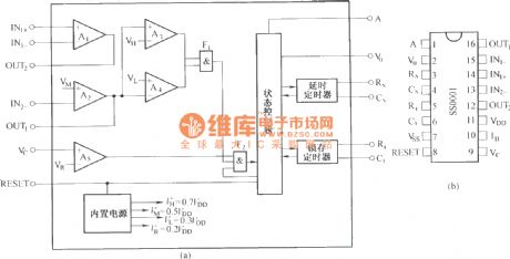
SS0001 is a general-purpose sensor control circuit. It not only matches with the output of pyroelectric infrared sensor perfectly, but also matches with a variety of other sensors. (View)
View full Circuit Diagram | Comments | Reading(1222)
LC9301/9305 infrared remote control emmitting and receiving integrated circuit diagram
Published:2011/9/27 22:52:00 Author:Rebekka | Keyword: infrared remote control , emmitting and receiving integrated circuit
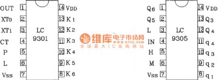
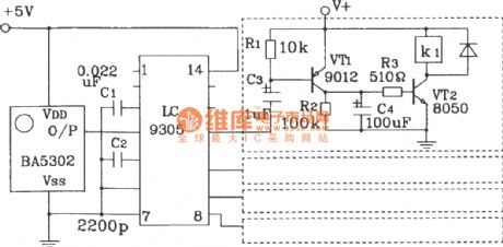
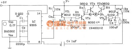
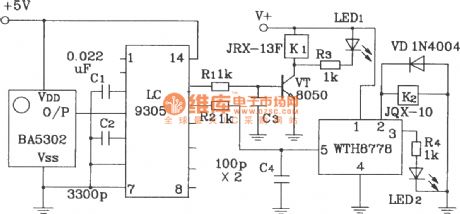
LC9301/9305 IC is an oscillator within encoder and infrared remote control special driver device. It can transimit 4 single codes, each single code will transimit 3 group of coding pulse train signal each time continuously. It improves the reliability of launch information.
The power supply range of LC9301/9305 infrared remote control transmitter/receiver is 4.5~5.5V. The typical value is 5V. External crystal frequency is 4555kHz. Carrier frequency is 38kHz. Their current consumption level is only μA. Transmitter circuit output current is greater than 5mA. It can drive infrared transmitting tube to work directly. The working distance is not less than 8m.
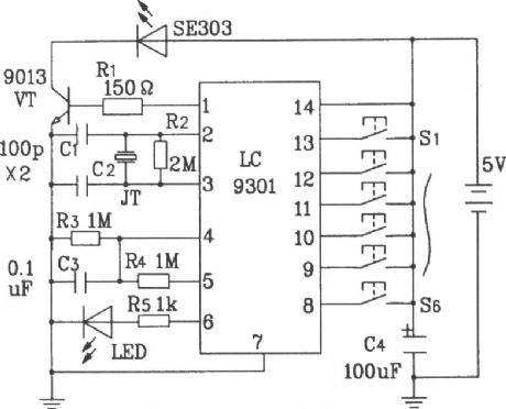
Typical application infrared remote control transmitter circuit composed of LC9301.
Typical application infrared remote control receiver circuit composed of LC9305.
DC motor forward and reverse remote control receiver circuit composed of LC9305.
Remote relay control bistable trigger circuit composed of LC9305. (View)
View full Circuit Diagram | Comments | Reading(1561)
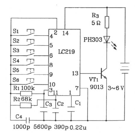
LC219/220 internal circuitry and pin function circuit diagram
Published:2011/9/27 22:21:00 Author:Rebekka | Keyword: internal circuitry , pin function
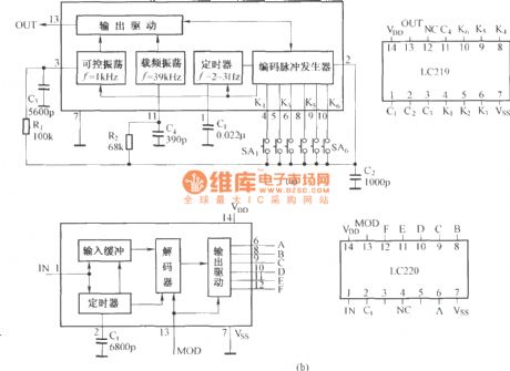
LC219 is a multi-purpose remote coding circuit, not only for the infrared remote control, but also for ultrasonic and radio remote control circuit, and itcan be used to double the wired remote control circuit,it isshown in figure (a). When it is used in radio-controlled, because radio remote control circuit board is specially equipped with the frequency of the oscillator circuit, then the foot can connect ⑩ ground, so that the internal carrier frequency oscillator circuit to stop working. LC220 is the supporting decoder circuit of LC219. It includes the internal buffer circuit, decoder, output circuit and timer, and itisshown in figure (b). (View)
View full Circuit Diagram | Comments | Reading(1201)
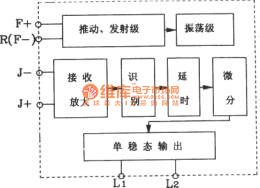
Direct infrared remote control switch circuit diagram composed of LS-2
Published:2011/9/27 22:15:00 Author:Rebekka | Keyword: direct , infrared remote control, switch
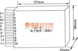
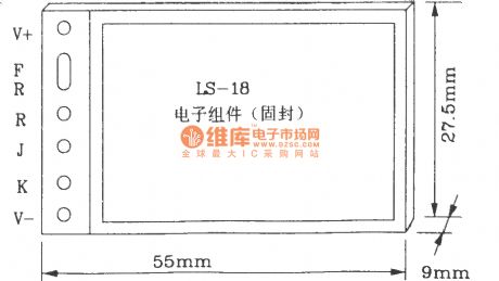
LS-2 remote control switch infrared sensor module is basically the same with the LS-18, in addition, it isused as a reflector.
LS-2 Pin diagram form
LS-2 internal block diagram
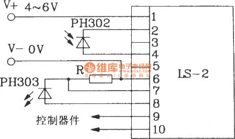
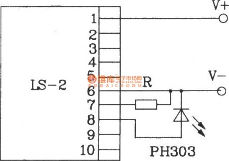
Electrical parameters LS-2 remote control switch module operating voltage is 4 ~ 6V (DC), typical value is 5V; Operating current is 2 ~ 4mA; Control output terminal (L1, L2) output voltage is4 ~ 6V; Input, output current is 50mA, reflection part of the power consumption is less than 1.5mA; Ip-p reflex drive capability is greater than 50mA; When it is used as a reflection, the reflection distance is 4 ~ 100cm, corresponding external current limiting resistor is 510Ω ~ lkΩ; When it is used as the direct infrared remote control switch, the maximum remote control distance is up to 8m.
Here is the basic application circuit of LS-2.
This circuit remote control distanceis up to 5 ~ 8m
(View)
View full Circuit Diagram | Comments | Reading(2009)
Typical application circuit diagram of LS-18 infrared sensor remote control switch module
Published:2011/10/17 20:53:00 Author:Rebekka | Keyword: Typical application , infrared sensor , remote control, switch module

(View)
View full Circuit Diagram | Comments | Reading(1156)
MC145026 ~ MC145030 pin function chart
Published:2011/9/27 21:47:00 Author:Rebekka | Keyword: pin function chart
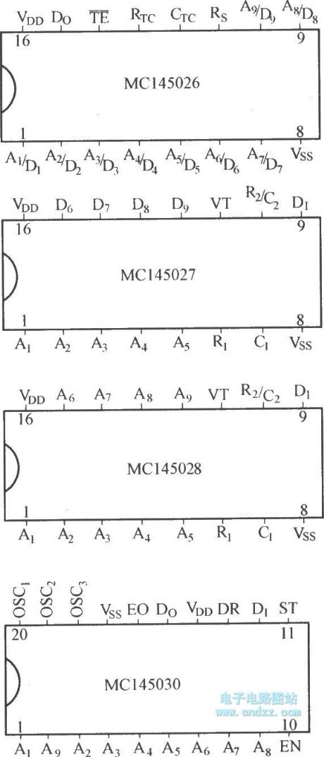
The digital encoding and decoding circuits has different kinds, andMC140000 series is one of them. The series ofcircuit includes MC145026, MC145027, MC145028, MC145029, and MC145030, etc. MC145026 is encoder, MC145027, MC145028 and MC145029 are decoders. MC145030 encoder can be used for the decoder, coding / decoding circuit. (View)
View full Circuit Diagram | Comments | Reading(1202)
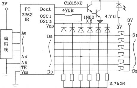
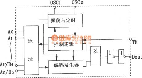
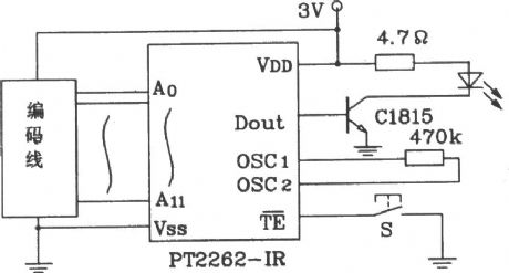
PT2262 IR and PT2272 Infrared remote control transmitter and receiver integrated circuit diagram
Published:2011/9/27 21:43:00 Author:Rebekka | Keyword: integrated circuit, Infrared remote control transmitter and receiver
(View)
View full Circuit Diagram | Comments | Reading(7879)
MNl5245SAY (TV) remote microprocessor
Published:2011/10/17 20:58:00 Author:Rebekka | Keyword: remote microprocessor

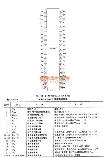

Technical Features:It uses CMOS manufacturing process.Execut one instruction costs 1.91μs.It uses 42 feet dual-in line plastic package.Matching models are LC7462 and CX20106A.
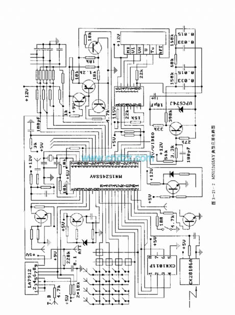
MN15245SAY pinout symbol and function.
Typical application circuit.
(View)
View full Circuit Diagram | Comments | Reading(2161)
Infrared remote control motor speed regulation transmitter and receiver circuit composed of LC219/220A
Published:2011/10/17 22:49:00 Author:Rebekka | Keyword: infrared remote control, motor speed regulation , transmitter and receiver circuit
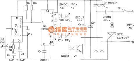
LC219 form infrared remote control motor speed regulation transmission circuit.
LC220A forms theinfrared remote control motor speed regulation receiving circuit.
Theinfrared remote control 5-block motor speed regulation circuithas little components for external rotation. It is simple debugging. The resonant frequency is 39kHz.
(View)
View full Circuit Diagram | Comments | Reading(2677)
Infrared remote control household appliances outlet circuit diagram
Published:2011/9/27 1:48:00 Author:Rebekka | Keyword: Infrared remote control, household appliances outlet
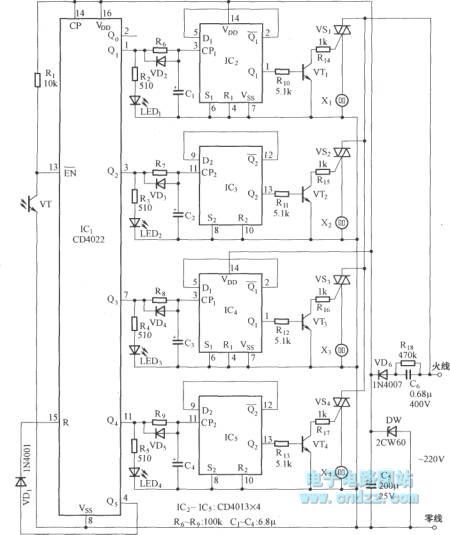
IC1 can use CD4022 or CD4017; IC2 ~ IC5 use dual D flip-flop CD4013; Optical transistor VT1 uses 3DU5; VT2 ~ VT5 use 9013, β> 80; VD2 ~ VD5 select several IN4148; Optional parameters is TRIAC 1A / 400V TRIAC; LED1 ~ LED5 LED are channel indication LED,they can use Φ5mm red LED.
(View)
View full Circuit Diagram | Comments | Reading(1938)
| Pages:450/2234 At 20441442443444445446447448449450451452453454455456457458459460Under 20 |
Circuit Categories
power supply circuit
Amplifier Circuit
Basic Circuit
LED and Light Circuit
Sensor Circuit
Signal Processing
Electrical Equipment Circuit
Control Circuit
Remote Control Circuit
A/D-D/A Converter Circuit
Audio Circuit
Measuring and Test Circuit
Communication Circuit
Computer-Related Circuit
555 Circuit
Automotive Circuit
Repairing Circuit