
Circuit Diagram
Index 456
RC bridge oscillating circuit with regulating ring
Published:2011/8/19 2:28:00 Author:Jessie | Keyword: RC bridge oscillating, regulating ring
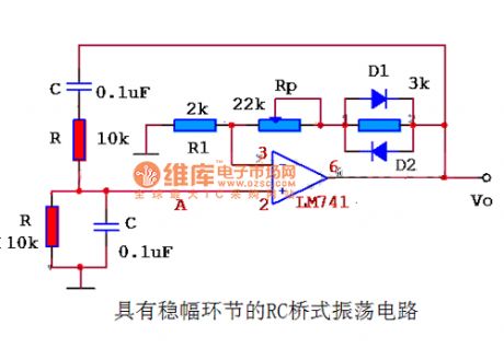
Connectingregulating ring to circuit, and adjusting potentiometer Rp, then you can use an oscilloscope to observe the output wave of oscillator circuit and the change of oscillating circuit's output wave, we will realize the influence of stability of regulating ring to sinusoidal oscillator circuit performance. (View)
View full Circuit Diagram | Comments | Reading(833)
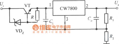
High input-high output integrated regulated power supply circuit circuit diagram 4
Published:2011/8/19 2:29:00 Author:Jessie | Keyword: High input-high output , integrated regulated power supply
View full Circuit Diagram | Comments | Reading(792)
SA866 pin array diagram
Published:2011/4/10 22:50:00 Author:may | Keyword: pin array
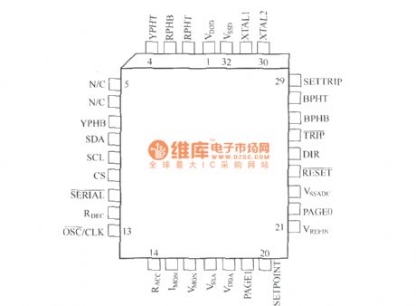
SA866 is special asynchronous machine SPWM control IC. It integrates kinds of protection function except generate SPWM pulse which is meeting requirements according to setup parameter. It also can fast cut off SPWM pulse in emergency, to protect frequency conversion power supply and load.
(View)
View full Circuit Diagram | Comments | Reading(1023)
Temperature monitoring alarm equipment circuit
Published:2011/4/14 6:43:00 Author:may | Keyword: Temperature monitoring, alarm equipment
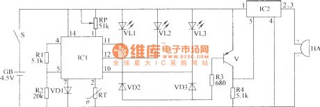
The temperature monitoring alarm equipment circuit introduced in this example has high , middle , low 3 gear temperature indication. It can send out alarm signal when the temperature is too high or too low. It can use in the occasion of big-arch shelter, greenhouse, etc which is needing temperature control.
This temperature monitoring alarm equipment consists of temperature monitoring/indication circuit and voice alarm circuit. The circuit is shown in the diagram.
Theoptions of components
R1~R4 chooses 1/4W metal-film resistor or carbon film resistor.
RP chooses compound film resistor or variable resistor.
VD1~VD3 all choose 1N4148 type silicon switching diode.
VL1~VL3 all choose Φ3mm LED
V chooses S8550 or 3CG8850 type silicon PNP transistor.
IC1 chooses ZH-3 type photometry application specific integrated circuit.
HA chooses DC electric magnetic buzzer with internal alarm voice source. (View)
View full Circuit Diagram | Comments | Reading(1012)
Electronic transformer with dependable performance
Published:2011/4/14 6:52:00 Author:may | Keyword: Electronic transformer, dependable performance
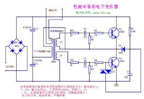
The circuit can steady work to consult the circuit diagram with no changes. Output voltage is 11V-13V, output current is 6A, working frequency is 60kHz. It can change working frequency by changing the numerical value of C3, C4, R1, R2. Its no-load current is very small.
(View)
View full Circuit Diagram | Comments | Reading(4495)
Parallel push-pull voltage changer
Published:2011/4/14 6:52:00 Author:may | Keyword: Parallel push-pull, voltage changer
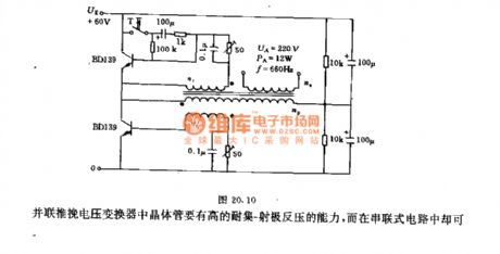
This circuit adopts two capacitors with 100μF to make up man-made star point. When shutting off, this circuit can prevent transistor from destroying by high back voltage. Using regulation resistance with 50Ω can adjust the turn on level of transistor. The usage of 0.1μF capacitor is toincrease thespeed of on-off.
The data of transformer:
Winding np= 160turns, 0.5mm copper lacquered wire
nr= 13turns, 0.2mm copper lacquered wire
ng= 1300turns, 0.15mm copper lacquered wire
The transistor in parallel push-pull transformer should have the ability of high withstand collector-emitter back voltage.
(View)
View full Circuit Diagram | Comments | Reading(811)
Voltage changer controls frequency by blocking oscillator
Published:2011/4/14 6:50:00 Author:may | Keyword: Voltage changer, blocking oscillator
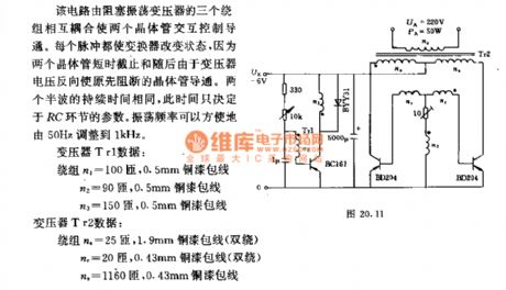
This circuit is mutual coupling by three windings of blocking oscillator transformer. This let two transistors in turns tocontrol and turn on. Each pulse can change the state of transformer, because two transistors cut off in a short time, and, later the transistor which is cutting off before is turn on because the voltage of transformer is reversing. The duration of two half-wave is the same. This time depends on the parameter of RC link. The oscillation frequency can easily adjust from 50Hz to 1kHz.
Data of transformer Tr1:
Wing n1= 100turns, 0.5mm copper enameled wire
n2= 90turns, 0.5mm copper enameled wire
n1= 150turns, 0.5mm copper enameled wire
Data of transformer Tr2:
Wing na= 25turns, 1.9mm copper enameled wire (double wrap)
nr= 20turns, 0.43mm copper enameled wire (double wrap)
na= 1160turns, 0.43mm copper enameled wire (View)
View full Circuit Diagram | Comments | Reading(1335)
Switching supply driving transformer
Published:2011/4/14 6:48:00 Author:may | Keyword: Switching supply, driving transformer
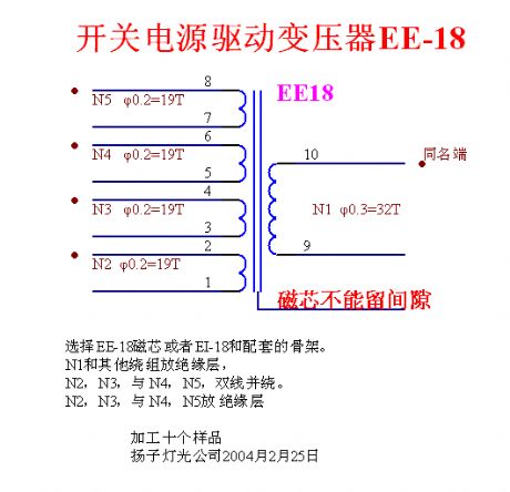
The introduction of winding coiling of high frequency transformer (switching supply driving transformer)
Switching supply driving transformer EE-18
We can choose EE-18 magnetic core or the assorted skeleton of EI-18.
One can put N1 and others winding in insulating barrier,
N2, N3 double winding along with N4, N5.
N2, N3, and N4, N5 is in insulating barrier. (View)
View full Circuit Diagram | Comments | Reading(746)
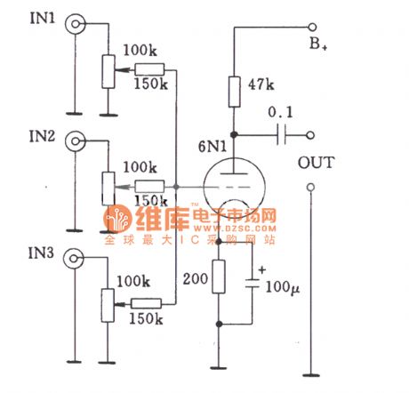
Single-stage multi-channel input circuit of tube by coupling resistor
Published:2011/10/14 1:44:00 Author:Ecco | Keyword: Single-stage , multi-channel input, coupling resistor
View full Circuit Diagram | Comments | Reading(689)
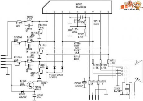
TDA6103 video amplifier circuit diagram
Published:2011/10/14 3:14:00 Author:Ecco | Keyword: video amplifier
View full Circuit Diagram | Comments | Reading(3203)
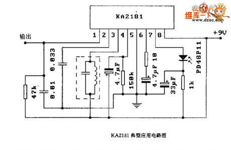
KA2181 application circuit diagram
Published:2011/10/16 21:57:00 Author:Ecco | Keyword: application circuit
View full Circuit Diagram | Comments | Reading(1119)
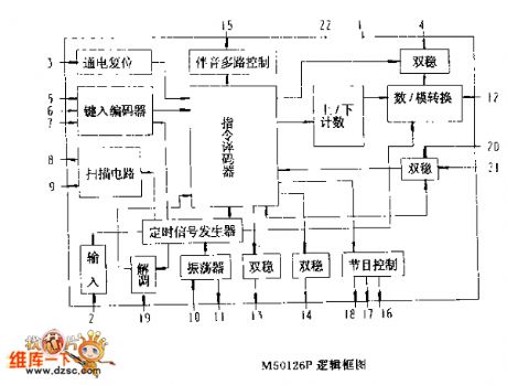
M50126P logic frame circuit diagram
Published:2011/10/16 22:26:00 Author:Ecco | Keyword: logic frame
View full Circuit Diagram | Comments | Reading(738)
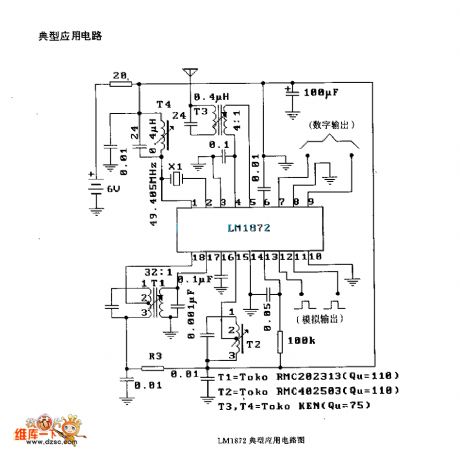
LMl872 application circuit diagram
Published:2011/10/16 22:25:00 Author:Ecco | Keyword: application circuit
View full Circuit Diagram | Comments | Reading(610)
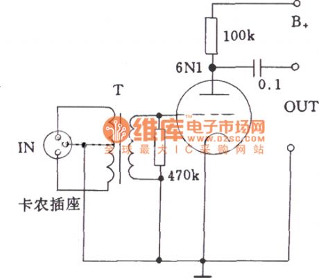
Low-impedance input circuit diagram of tube
Published:2011/10/14 1:39:00 Author:Ecco | Keyword: Low-impedance input, tube
View full Circuit Diagram | Comments | Reading(725)
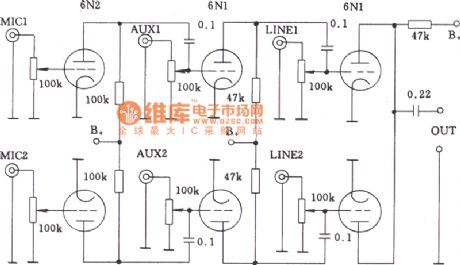
Multi-channel audio input mixing circuit of tube
Published:2011/10/14 1:52:00 Author:Ecco | Keyword: Multi-channel, audio input mixing
View full Circuit Diagram | Comments | Reading(772)
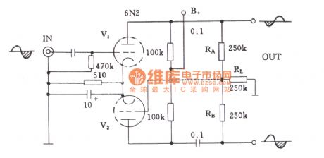
Common-anode loaded inverter circuit of tube
Published:2011/10/14 1:50:00 Author:Ecco | Keyword: Common-anode loaded inverter
View full Circuit Diagram | Comments | Reading(729)
The typical self-bias power amplifier stage circuit of tube
Published:2011/10/14 1:48:00 Author:Ecco | Keyword: self-bias , power amplifier , tube
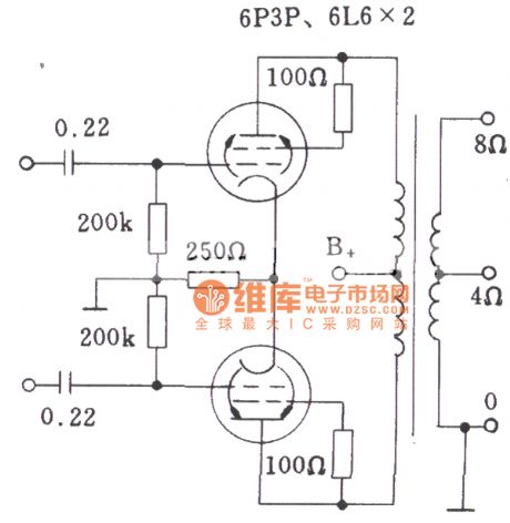
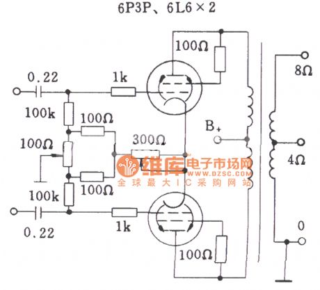
The typical self-bias power amplifier stage circuit withoutdebugging of tube
The typical semi-debugself-bias power amplifier stage circuit of tube
(View)
View full Circuit Diagram | Comments | Reading(1475)
The shape circuit of common potentiometer
Published:2011/10/14 1:42:00 Author:Ecco | Keyword: shape, common potentiometer
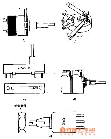
a). b): potentiometer with switch
c): Slide potentiometer
d): asynchronous different double-axis potentiometer
e): locking-type potentiometer (View)
View full Circuit Diagram | Comments | Reading(998)
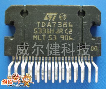
TDA7386 IC
Published:2011/10/14 2:03:00 Author:Ecco
View full Circuit Diagram | Comments | Reading(1673)
TDA7388 IC
Published:2011/10/14 2:03:00 Author:Ecco | Keyword: IC
View full Circuit Diagram | Comments | Reading(3995)
| Pages:456/2234 At 20441442443444445446447448449450451452453454455456457458459460Under 20 |
Circuit Categories
power supply circuit
Amplifier Circuit
Basic Circuit
LED and Light Circuit
Sensor Circuit
Signal Processing
Electrical Equipment Circuit
Control Circuit
Remote Control Circuit
A/D-D/A Converter Circuit
Audio Circuit
Measuring and Test Circuit
Communication Circuit
Computer-Related Circuit
555 Circuit
Automotive Circuit
Repairing Circuit