
Circuit Diagram
Index 447
Goods anti-theft annunciator circuit diagram ( transceiver module composed of RCMlA/RCMlB)
Published:2011/10/19 22:18:00 Author:Rebekka | Keyword: Goods anti-theft annunciator
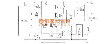
Emitter is composed of RCM1A and battery. Receiver is composed of receiver module RCM1B with double-delay function, high-voltage generator and the alarm circuit. (View)
View full Circuit Diagram | Comments | Reading(2140)
Radio remote control transmitter and receiver head circuit diagram
Published:2011/10/18 2:04:00 Author:Rebekka | Keyword: Radio remote control , transmitter and receiver head
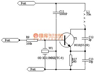
The circuits of transmitting part and receiving part are shown as above.
Radio remote control transmitter T630 is a micro-transmitter without the signal. Its emission frequency is 265MHz, and the power supply is 12V. Remote control distance is 100M, operating current is only 4mA, the volume is 28X12X10mm. Radio receiver T631has a built-in antenna. It is the samewith the TV tuner receiver, demodulator. Its typical operating voltage is 6V. Its waiting current is 1mA. Receiver frequency is 265MHz, its volume is only 31X23X10mm. They can be easily used to produce a variety of radio-controlled device with the features of miniaturization, transmission distance, power consumption, anti-interference ability and so on. They can easily replace the infrared, ultrasonic transmitter and receiver. Radio head T630 circuit is shown as below. Four launch tubes V1 circuit and external components C1, C2, L1, L2 constitute a frequency of 265MHz ultra-high frequency transmitter circuit L2. (View)
View full Circuit Diagram | Comments | Reading(4712)
Wireless remote electric car circuit diagram
Published:2011/10/18 1:57:00 Author:Rebekka | Keyword: Wireless remote electric car
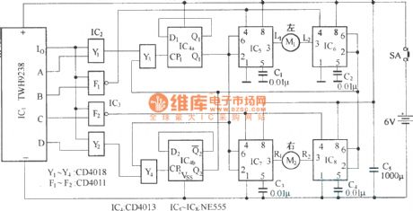
The electric model car remote controller can make model car go forward, astern and also turn right or left. The structure is simple and easy to operate. The radio remote control receiver demodulation circuit uses TWH9238 components. The supporting remote control transmitter components TWH9236 is shown in the figure. (View)
View full Circuit Diagram | Comments | Reading(5738)
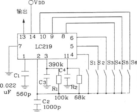
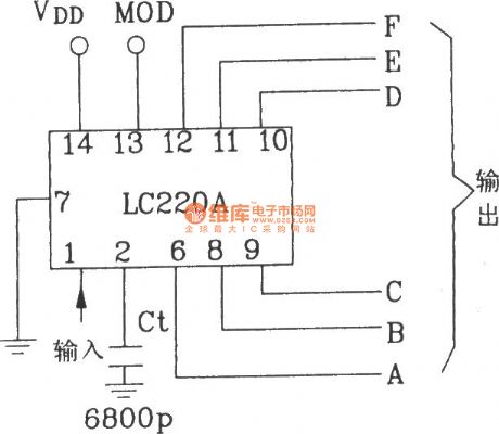
Ultrasonic 6-road remote control receiver application circuit composed of LC219/220A
Published:2011/10/17 22:30:00 Author:Rebekka | Keyword: Ultrasonic , 6-road , remote control receiver
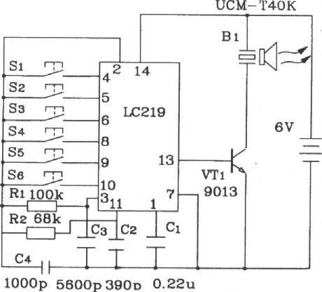
6 channel remote control transmitter of ultrasonic application circuit composed of LC219.
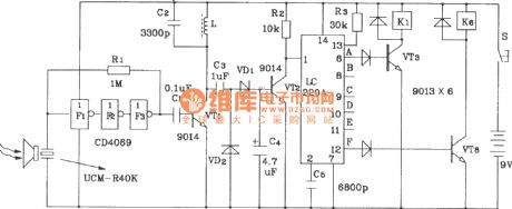
6-channel remote control receiver of ultrasonic application circuit composed of LC220A.The 13-foot of LC219 circuit outputs 39kHz carrier encoder pulse. The MOD of the receiving circuit LC220 connectsto a self-locking way. (View)
View full Circuit Diagram | Comments | Reading(2964)
LA4287 audio circuit diagram
Published:2011/10/17 22:05:00 Author:Rebekka | Keyword: audio circuit
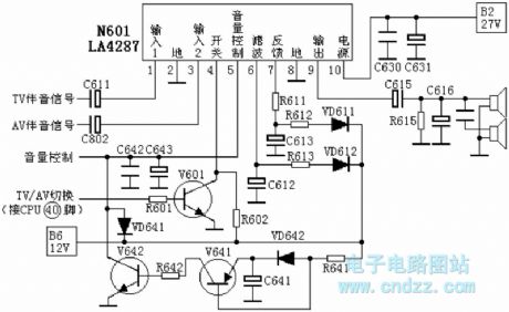
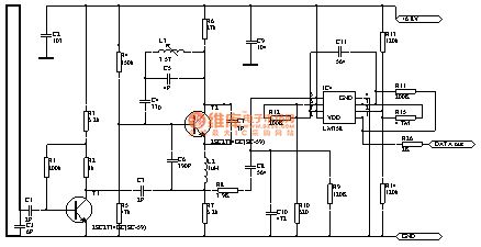
TV sound signal isinput from the N601's pin 1, andAV audio signal is input from the N601's pin 3. The TV/AV switching signal output by CPU(40)feet bypassing the base ofR601 to V601. Thepin 4 isinverted by V601 chosen by the internal and output signal through N601 pin 9. Then itmakes the speaker sound. The shutdown audio squelch circuit is composed of V641 and V642. In the normal boot, 12V voltage passes R641, then it isadded to the base of V641 and the emitter VD642. Due to the existence of VD642, V641 base voltage is 0.7V, which ishigher than high-emitter voltage. V641 and V642 are stopped. The loop has no influence on volume control.
1 pin: 6.3V-- signal input 12 pin: 0V - to 3 pin: 6.3V-- signal input 24 pin: 2.1V-- signal switch 5 pin: 0.67V-- volume control voltage input6 pin: 9.8V-- Filter 7 pin: 9.8V-- Feedback 8 pin: 0V - to 9 pin: 9.9V-- output pin 10 pin: 21V - Power Supply (View)
View full Circuit Diagram | Comments | Reading(11529)
Typical remote control transmitter and receiver application circuit composed of LC219/LC220A
Published:2011/10/17 22:01:00 Author:Rebekka | Keyword: remote control , transmitter, receiver
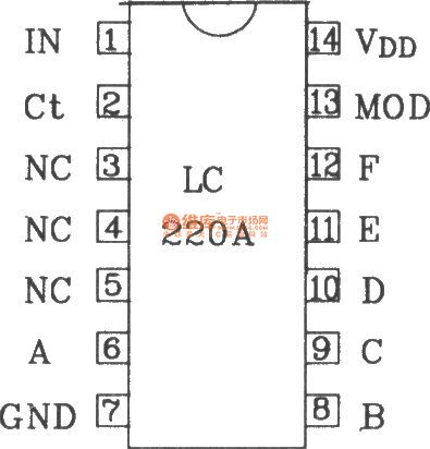
LC219/LC220A is a multi-function remote control transmitter / receiver integrated circuit. It is generally used in electric fans shift, wave side of the conversion, home appliances and toys, remote control rolling circuit.
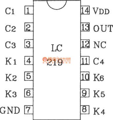
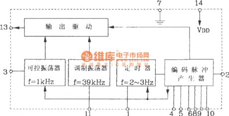
LC219 transmitter chip block diagram
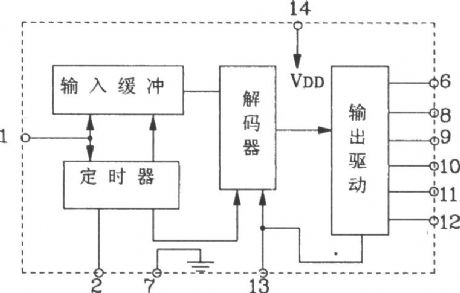
LC219 transmitter chip supply voltage range is 2.5 ~ 6V; Quiescent operating current is less than 5μA; Output drive current IoH ≥ 2mA, IoL ≥ 300μA. It is applicable to high-driven work NPN transistor; Repetition rate of the internal timer is 2 ~ 3Hz, controllable oscillation frequency is lkHz, duty cycle is 50%, pulse width is 0.5ms: modulation oscillation frequency range is 32 ~ 48kHz, Generally it uses 39kHz appropriate election. LC220A receiver chip supply voltage is 4.5 ~ 9V; Quiescent operating current is less than 5μA; Each output drive current is IoH ≥ 2mA, Ioc ≥ lmA; Output short-circuit current is IOH (S) ≥ 8mA, IOL (S) 5mA. It can be connected with LED drive directly or transistors.
(View)
View full Circuit Diagram | Comments | Reading(2216)
KL3 microwave electronic switching circuit diagram
Published:2011/10/17 21:57:00 Author:Rebekka | Keyword: microwave electronic switching circuit
KL3 microwave electronic switch is made by using doppler effect of electromagnetic wave theory. The entire circuit is encapsulated in a plastic case. The outside has four lead lines. 2 of red lead lines areconnected to AC 220V power supply. 2 green lead lines are connected to controlled load. It is suitable for automatic control of lighting or anti-theft alarm device. (View)
View full Circuit Diagram | Comments | Reading(1320)
Four-action RF remote transmitter and receiver circuit composed of KIA6933S/6957P
Published:2011/10/17 21:55:00 Author:Rebekka | Keyword: four-actions RF remote, transmitter , receiver
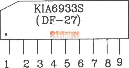
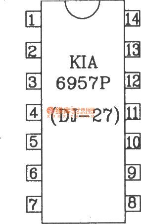
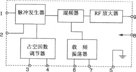
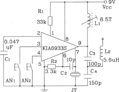
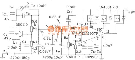
The internal RF remote control transmitter KIA6933S is composed of pulse generator within the integrated circuit KIA6933S, the duty factor regulator, mixer, oscillator and RF carrier frequency amplifier. The remote control transmitter circuit composed of it hasmany features, such assimpleexternal rotation circuit, easy to debugging. Usually 4 states remote controls can be achieved. The internal KIA6957P receiving circuit has two low-frequency amplification units, integration circuit and signal comparison detection circuit. Since there is not high-frequency receiving circuit, it uses high-frequency super-regenerative receiver circuit. The similar types of circuits are: DF-27/DJ-27, TA7333P/TA7657P.
(View)
View full Circuit Diagram | Comments | Reading(2611)
4096 single-function remote control transmitter, receiver application circuit composed of KD-12E/KD-12F
Published:2011/10/17 21:35:00 Author:Rebekka | Keyword: single-function , remote control , transmitter and receiver
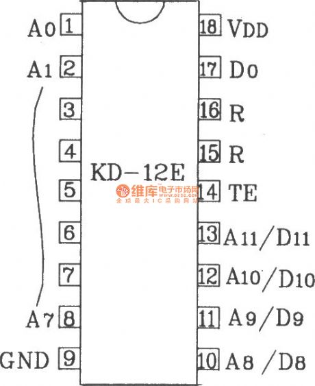

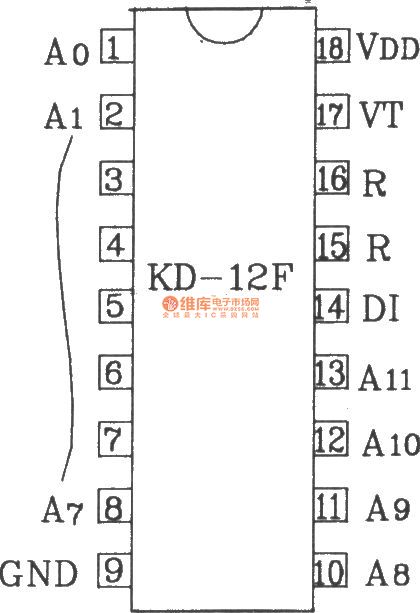
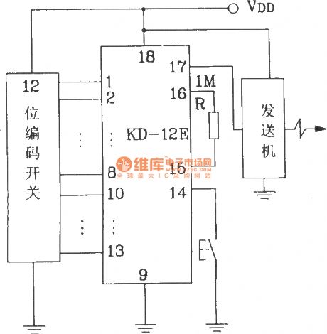
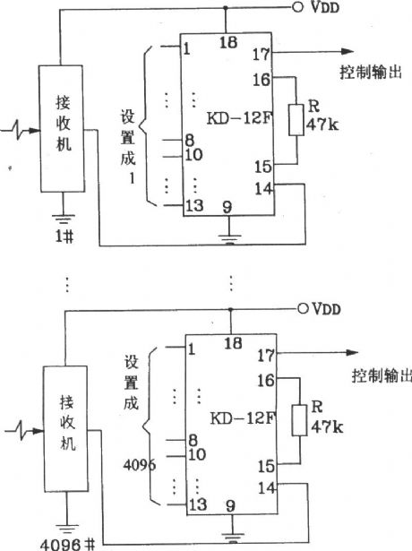
KD-12E/KD-1290 transistor devices are made in the factory in Zhejiang, Xiaoshan for the latest remote control, telemetry dedicated encoding / decoding ICs. This circuit can simplify many complex remote control system and circuit detection system. It is a high reliability circuit. The current device has been widely used in home appliances, industrial control, alarm and robot control.
Electrical parameters: Since KD-12E and KD-12D (F) use CMOS process, therefore it has a wide operating voltage range, low power consumption. The typical operating voltage range is 2 ~ 5V, quiescent current (no oscillations) is 0.1 ~ 1μA. As A8/D8 ~ A11/D11 is used to control code input, each 256 code can have 16 seeds passwords. It can be completed by artificially setting different control functions.
(View)
View full Circuit Diagram | Comments | Reading(1591)
TA8211AH audio circuit diagram
Published:2011/10/17 21:29:00 Author:Rebekka | Keyword: audio circuit
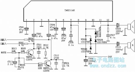
Changhong C2588 TVpin 1: 2.1V-- left channel negative-feedback external capacitor pin 2: 2.2V-- left channel signal input pin 3: 0V - ground pin 4: 2.2V-- right channel signal input pin 5: 2.1V-- right channel negative feedback external capacitor pin 6: 8.2V-- power supply filter pin 7: 12V - right channel signal outputpin 8: 2.2V-- empty pin 9: 24V - power supply pin 10: 0V - ground (PA) pin 11: 2.2V-- empty pin 12: 12V - left channel signal output (View)
View full Circuit Diagram | Comments | Reading(3717)
TDA8145 pincushion correction circuit diagram
Published:2011/10/17 21:24:00 Author:Rebekka | Keyword: pincushion correction
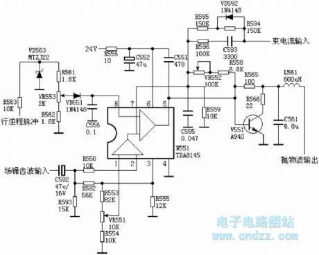
TDA8145 is a widely used pincushion correction special IC. Its basic working principle is as follow: Field sawtooth voltageis sentto the N551's (2) feet by passing C592, R550. VR552 is the pillow distortion correction adjustment potentiometer. Adjusting it essentially can change the the amount of negative feedback from N551's 5 feet to 7, and it changes the pin 5 sparabolic wave output voltage rangeto make themoderate correction. There is not distortion of grating to keep rectangular state. VR553 is theline adjusting potentiometer.
(View)
View full Circuit Diagram | Comments | Reading(10410)
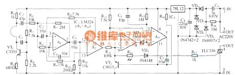
Eight-way wireless burglar alarm system circuit diagram
Published:2011/10/17 21:17:00 Author:Rebekka | Keyword: Eight-way wireless burglar alarm system

(a) shows the alarm monitoring and emission extension, KD9562 forms the alarm monitoring station launchesby 8 trigger terminals. The security monitoring circuit is composed of pyroelectric infrared detector module HL911L. When the situation occurs. HL911L's pin ① outputs high level. Then you can turnon the electronic switch to connect the internal circuit of TWH8778. TWH8778's pin ③ outputs high level, then the relay K is pulled in. Contaction switch KSwill makeemission component FDD5 work. (B) shows the host alarm receivingcircuit. When JDD5 gets the alarm signal sent by alarm extension. It will be demodulated. When JDD5 receives the alarm signal sent by the police station. The signal output by the output terminal is audio signal. It will make alarm sound through speaker. (View)
View full Circuit Diagram | Comments | Reading(1809)
820e computer motherboard circuit diagram 65
Published:2011/10/23 20:42:00 Author:Ecco | Keyword: computer motherboard
View full Circuit Diagram | Comments | Reading(833)
820e computer motherboard circuit diagram 64
Published:2011/10/23 20:41:00 Author:Ecco | Keyword: computer motherboard
View full Circuit Diagram | Comments | Reading(751)
820e computer motherboard circuit diagram 63
Published:2011/10/24 19:54:00 Author:Ecco | Keyword: computer motherboard
View full Circuit Diagram | Comments | Reading(873)
820e computer motherboard circuit diagram 55
Published:2011/10/24 19:57:00 Author:Ecco | Keyword: computer motherboard
View full Circuit Diagram | Comments | Reading(887)
820e computer motherboard circuit diagram 54
Published:2011/10/24 19:56:00 Author:Ecco | Keyword: computer motherboard
View full Circuit Diagram | Comments | Reading(836)
845ddr computer motherboard circuit diagram 46
Published:2011/10/19 2:20:00 Author:Ecco | Keyword: computer motherboard
View full Circuit Diagram | Comments | Reading(870)
820e computer motherboard circuit diagram 66
Published:2011/10/23 20:42:00 Author:Ecco | Keyword: computer motherboard
View full Circuit Diagram | Comments | Reading(856)
820e computer motherboard circuit diagram 67
Published:2011/10/23 20:43:00 Author:Ecco | Keyword: computer motherboard
View full Circuit Diagram | Comments | Reading(1261)
| Pages:447/2234 At 20441442443444445446447448449450451452453454455456457458459460Under 20 |
Circuit Categories
power supply circuit
Amplifier Circuit
Basic Circuit
LED and Light Circuit
Sensor Circuit
Signal Processing
Electrical Equipment Circuit
Control Circuit
Remote Control Circuit
A/D-D/A Converter Circuit
Audio Circuit
Measuring and Test Circuit
Communication Circuit
Computer-Related Circuit
555 Circuit
Automotive Circuit
Repairing Circuit