
Circuit Diagram
Index 440
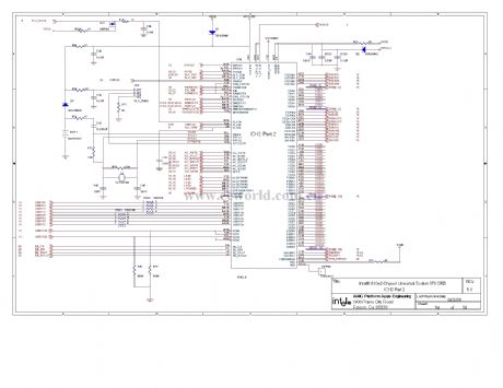
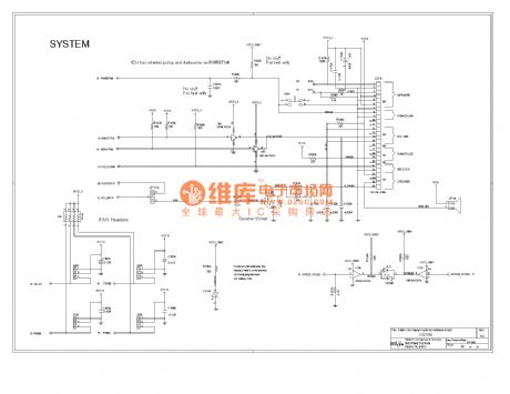
810 computer motherboard circuit diagram 14
Published:2011/10/25 21:58:00 Author:Ecco | Keyword: computer motherboard
View full Circuit Diagram | Comments | Reading(936)
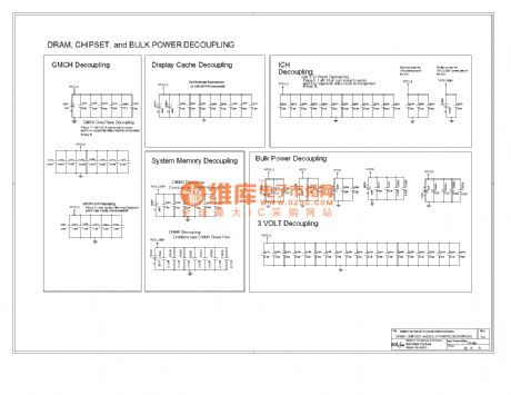
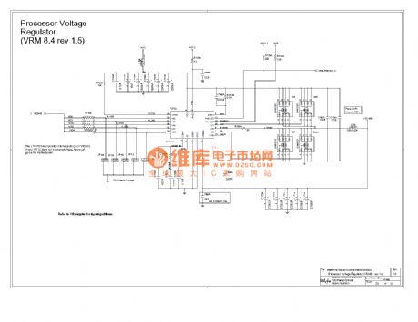
810E computer motherboard circuit diagram 33
Published:2011/10/27 1:56:00 Author:Ecco | Keyword: computer motherboard
View full Circuit Diagram | Comments | Reading(838)
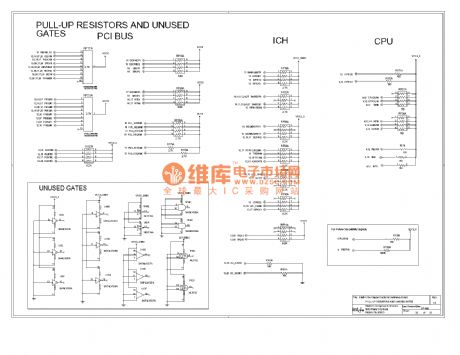
810E computer motherboard circuit diagram 32
Published:2011/10/27 1:55:00 Author:Ecco | Keyword: computer motherboard
View full Circuit Diagram | Comments | Reading(785)
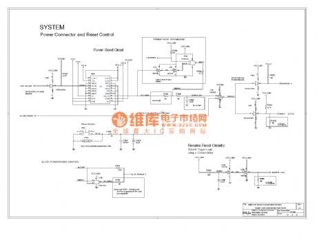
810E computer motherboard circuit diagram 31
Published:2011/10/27 1:55:00 Author:Ecco | Keyword: computer motherboard
View full Circuit Diagram | Comments | Reading(1128)
810E computer motherboard circuit diagram 30
Published:2011/10/27 1:54:00 Author:Ecco | Keyword: computer motherboard
View full Circuit Diagram | Comments | Reading(892)
810E computer motherboard circuit diagram 29
Published:2011/10/27 1:54:00 Author:Ecco | Keyword: computer motherboard
View full Circuit Diagram | Comments | Reading(948)
810E computer motherboard circuit diagram 28
Published:2011/10/27 1:53:00 Author:Ecco | Keyword: computer motherboard

View full Circuit Diagram | Comments | Reading(951)
Panasonic 973 air conditioning remote control circuit diagram
Published:2011/9/16 1:11:00 Author:Rebekka | Keyword: Air conditioning remote control, Panasonic
View full Circuit Diagram | Comments | Reading(2869)
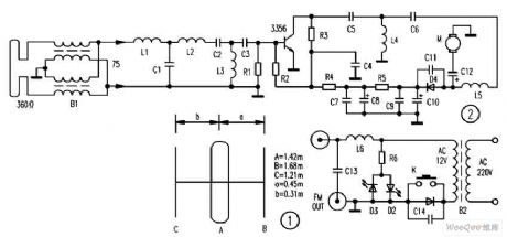
FM broadcast special-purpose electric wire circuit diagram
Published:2011/10/20 21:09:00 Author:Rebekka | Keyword: FM broadcast , special-purpose electric wire
View full Circuit Diagram | Comments | Reading(1659)
TDA2009 mono and stereo audio power amplifier circuit diagram
Published:2011/10/20 21:12:00 Author:Rebekka | Keyword: mono , stereo audio , power amplifier

Pin 1: 1.2V-- left channel input Pin 2: 0.8V-- left channel feedback Pin 3: 12V - Squelch Pin 4: 0.8V--right channel feedback Pin 5: 1.2V--right channel input
Pin 6: 0V - groundPin 7: 0V - empty Pin 8: 12.4V-- right channel outputPin 9: 24V - Power Pin 10: 12.4V-- left channel output (View)
View full Circuit Diagram | Comments | Reading(5049)
Audio amplifier circuit diagram composed of TDA1013
Published:2011/10/18 3:06:00 Author:Rebekka | Keyword: Audio amplifier

TDA1013 function and reference voltage Pin 1: 0V - to Pin 2: 7.7V-- audio outputPin 3: 16V - Power Pin 4: 13.5V-- Power Supply Pin 5: 0.3V-- Amplifier Input Pin 6: 6.7V-pre-outputPin 7: 2.8V-- Volume Control Pin 8: 1.9V-audio inputPin 9: 0V-ground (View)
View full Circuit Diagram | Comments | Reading(11206)
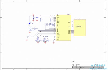
Time controller circuit diagram using CD4060
Published:2011/10/20 21:20:00 Author:Rebekka | Keyword: time controller
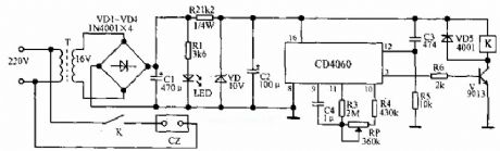
When the circuit gets power, it is connected instantaneously, and R5, C3 constitutes the differentiating circuit to guarantee delay time from zero. Under oscillator signal's influence, CD4060's internal counter starts to work, 3 feet is the 14th level counter's out port, if it makes 3 feet switches to the high level from low level, it needs t=213×2.2KC (second), and the low voltage of pin 3 causes the triode V closure. When delay time reaches, pin 3 jumps to high level from low level, then V is saturated breakover after being current limited by R6, and relay K pulls in, then the load gets the electricity. This electric circuit's delay time can be adjusted in 2.1~4 hours. (View)
View full Circuit Diagram | Comments | Reading(2865)
Electric single-girder crane radio remote control(TX315B1) circuit diagram
Published:2011/10/19 20:47:00 Author:Rebekka | Keyword: Electric single-girder crane , radio remote control
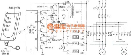
Four operation functions of the circuit: Mobile electric hoist travel hook (hanging objects) can do up and down movements. The right half part of the dotted line in the figureis the operation of cranes in the original circuit. K1 ~ K4 are the original manual operation buttons. Now they are used to replace the relay contacts, SQ is the improving limiting switch. KM1 ~ KM4 are the AC relays that are used to control the motor to enhance the motor M1 and M2. It controls and rises the forewardandreversal rotation of hanging objects. The dotted lines ofleft halfpart inthe figure form the new radio remote control circuit. In the circuit, the four output ends A ~ D of TX315B1 receiving circuit canrespectively drive tubes VT ~ VT4. (View)
View full Circuit Diagram | Comments | Reading(4109)
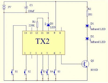
Multi-channel infrared remote control lighting
Published:2011/10/18 2:52:00 Author:Rebekka | Keyword: Multi-channel infrared, remote control lighting
View full Circuit Diagram | Comments | Reading(1839)
Multi-channel wireless remote control circuit(F36-F/F36-J)
Published:2011/10/19 22:34:00 Author:Rebekka | Keyword: Multi-channel, wireless remote control
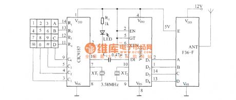
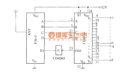
Remote control transmitter circuit.
Receiver decoding circuit.
The circuit is composedof F36-F/F36-J multi-channel radio remote control circuit. In the transmitter circuit, it usesDTMF encoding and decoding circuit to turn launch four-key input signal into a binary code inputand sent out by F36-F . In the receiver circuit, F36-J will receive the remote signal and pass demodulation decoding and reduce to four binary code. Four binary code passes a four - sixteen line decoder and turn to a four - sixteen line decoder. It controls a corresponding circuit.
(View)
View full Circuit Diagram | Comments | Reading(3208)
Wireless remote control plus and minus resistor network circuit diagram
Published:2011/10/19 22:15:00 Author:Rebekka | Keyword: Wireless remote control plus , minus resistor network
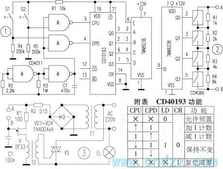
Transmitter circuit is shown in figure 1. CD40193 is a dual clock synchronous 4-bit binary up / down counter, andits function is shown as the table. CPU is the addition clock impulse input terminal, and CPD is a subtraction input of the clock pulse. When it inputs 0 to 15 pulses, its output terminals Q3 ~ Q0 change with the oder of 0000 ~ 1111 (addition) or 1111 ~ 0000 (subtraction). It is fired by the built-in antenna outside. CD4011 NAND chip is composed of two ultra-low frequency oscillators. The other two NAND gatesare the addition and subtraction counting gate. When the subtraction S1 door is open, CD40193 reduces the count. When the addition count door S2 is open, CD40193 starts the additional counts. The working voltage of CD4011 and CD40193 is 5V. Ultra-low frequency oscillator frequency is about 0.5 ~ 2Hz.
(View)
View full Circuit Diagram | Comments | Reading(2779)
Novel practical multi-channel infrared remote control switching circuit
Published:2011/10/19 22:06:00 Author:Rebekka | Keyword: Novel practical , multi-channel, infrared remote control, switching circuit
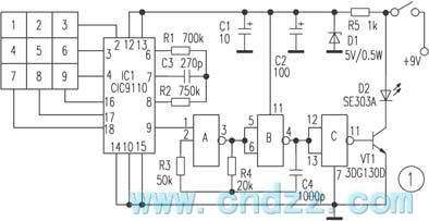
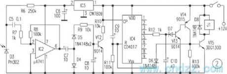
The teleswitch is reliable, and the debugging is simple, and it can realize nine-group control. It is used to remote control different household appliances and the remote control installments. The entire circuit is composed of transmission and receiving. Transmission circuit is shown in Figure 1, and the code is completed by pulse telephone number dialing integrated circuit CIC9110. When people presses down any number between“1~9”, the special-purpose pulse generator's pin ⑨ outputs high level pulse, and its speed may amount to for 20/seconds. These pulses are delivered directly to A's pin ①, its oscilation frequency approximately is 38kHz. (View)
View full Circuit Diagram | Comments | Reading(2727)
Remote control automatic door circuit diagram
Published:2011/10/19 21:21:00 Author:Rebekka | Keyword: Remote control automatic door
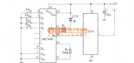
Transmitter circuit:
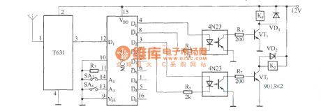
Receiving circuit:
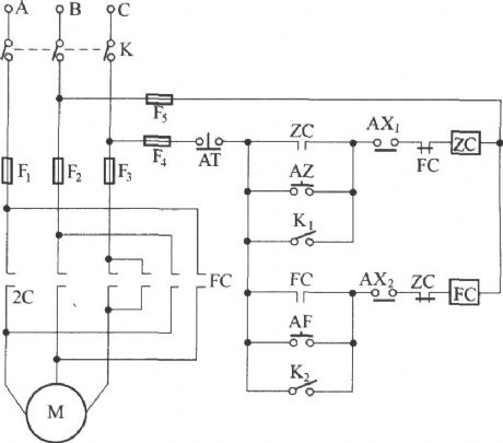
The circuit controlling three-phase motor forward and reversing rotation is shown as below.
(View)
View full Circuit Diagram | Comments | Reading(4370)
Voice remote control doorbell(transceiver module composed of RCMlA and RCMlB)
Published:2011/10/19 21:25:00 Author:Rebekka | Keyword: Voice remote control doorbell
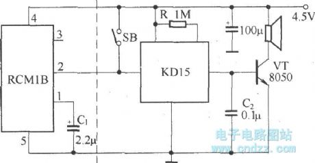
Remote control doorbell saves a connection between the placement of the doorbell and doorbell button. The place of doorbell is more convenient. Voice IC can use integrated soft KD15 series. After the installation of the circuit, it can be put into normal operation. People should keep the receiver away from large metal objects to avoidaffecting the sensitivity of remote control.
(View)
View full Circuit Diagram | Comments | Reading(1319)
Detection alarm circuit diagram composed of TWH9248/TWH9249
Published:2011/10/18 1:12:00 Author:Rebekka | Keyword: Detection alarm circuit
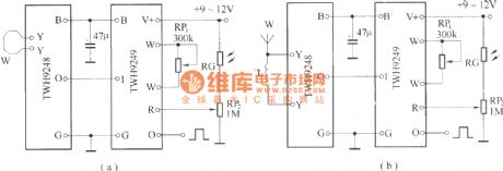
TWH9248/TWH9249 is a pair of microwave sensing components (also known as radar detectors). It is mainly used for movement detection of human body or object. The effective detection distance is 3-6 meters, voltage is 9-12V.
(View)
View full Circuit Diagram | Comments | Reading(1165)
| Pages:440/2234 At 20421422423424425426427428429430431432433434435436437438439440Under 20 |
Circuit Categories
power supply circuit
Amplifier Circuit
Basic Circuit
LED and Light Circuit
Sensor Circuit
Signal Processing
Electrical Equipment Circuit
Control Circuit
Remote Control Circuit
A/D-D/A Converter Circuit
Audio Circuit
Measuring and Test Circuit
Communication Circuit
Computer-Related Circuit
555 Circuit
Automotive Circuit
Repairing Circuit