
Circuit Diagram
Index 460
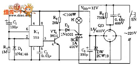
Delay energy-saving lighting circuit diagram
Published:2011/10/14 3:09:00 Author:Ecco | Keyword: Delay energy-saving lighting
View full Circuit Diagram | Comments | Reading(2409)
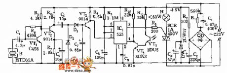
Optical double-control delay lamp circuit (1)
Published:2011/10/14 2:45:00 Author:Ecco | Keyword: Optical double-control , delay lamp
View full Circuit Diagram | Comments | Reading(799)
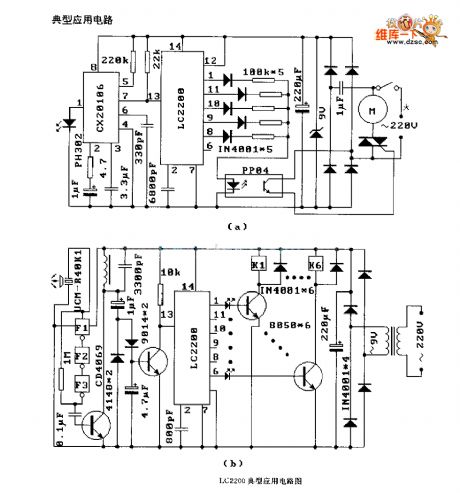
LJC2200 (air conditioner, electric fan, tape recorder) radio remote control receiver circuit
Published:2011/10/14 2:19:00 Author:Ecco | Keyword: air conditioner, electric fan, tape recorder, radio remote control , receiver
View full Circuit Diagram | Comments | Reading(2114)
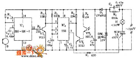
Optical double-control delay lamp circuit (2)
Published:2011/10/14 2:44:00 Author:Ecco | Keyword: optical double-control , delay lamp
View full Circuit Diagram | Comments | Reading(752)
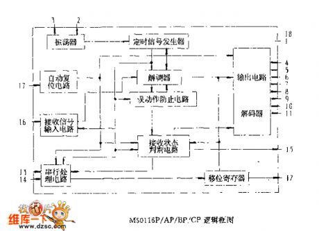
M50116P/AP/BP/CP logic box circuit
Published:2011/10/14 3:08:00 Author:Ecco | Keyword: logic box
View full Circuit Diagram | Comments | Reading(797)
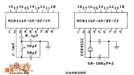
M50116P/AP/BP/CP oscillator connection circuit diagram
Published:2011/10/14 3:07:00 Author:Ecco | Keyword: oscillator connection
View full Circuit Diagram | Comments | Reading(769)
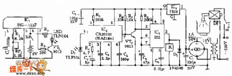
Shielding infrared automatical switching tap circuit
Published:2011/10/14 3:05:00 Author:Ecco | Keyword: Shielding infrared , automatical switching tap
View full Circuit Diagram | Comments | Reading(876)
Optical isolation circuit diagram using as scanner
Published:2011/9/15 21:21:00 Author:Rebekka | Keyword: Optical isolation , scanner
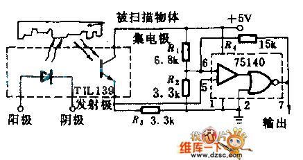
The circuit includes a TIL139 source / detector assembly and the 75140 line receiver. It can be used to makeresponse to reflected light or interruption light. With 5V power supply, the output is standard TTL level.Itinserts the 500Ω potentiometer between R1 and R2 to make the sensitivity be adjusted, then75140's pin(7)is connected to (3) and itgets the output from (1). You can reverse the output polarity. (View)
View full Circuit Diagram | Comments | Reading(1109)
Optical isolation circuit for isolating AC hum sound
Published:2011/9/15 21:25:00 Author:Rebekka | Keyword: Optical isolation , AC hum sound
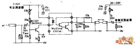
In the TV's audio feed-in line, it uses optical isolators to prevent ground current power frequency cycle. It protects the low-level signals from the exchange om sound interference. This circuit should be used for generating high-quality sound and video output of the modulator.The optical isolator uses the photosensitiveLinton tube and infrared light emitting diode. It uses 50KΩ variable resistor regulatorto adjustdiode current and get the best compromise between the noise and distortion. (View)
View full Circuit Diagram | Comments | Reading(3247)
The alarm circuit diagram of optical intensity controlling
Published:2011/9/15 21:27:00 Author:Rebekka | Keyword: alarm circuit, optical intensity controlling
The circuit is available for hunters, fishermen go for a job at dawn. By flashlight or inside lights this circuit can betriggered. So it can be used as fire and burglar alarm circuit. Only when the lights die out, the alarm will stop. (View)
View full Circuit Diagram | Comments | Reading(1550)
The circuit of mobile phone charger
Published:2011/9/26 1:12:00 Author:Rebekka | Keyword: Mobile phone charger
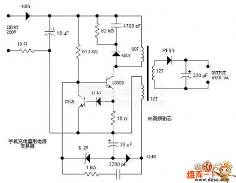
Here is the schematic diagram of the mobile phone charger circuit:
(View)
View full Circuit Diagram | Comments | Reading(7530)
Galaxy yh-250 v2.1 3.3v power supply circuit diagram
Published:2011/9/15 21:43:00 Author:Rebekka | Keyword: Galaxy , 3.3v power supply
It uses FETs q13, tl43l and the comparator Lm339 to form regulated voltage circuit. It is shown as the figure. The sawtooth signal of IC ka7500b's first pin ⑤ is sent by 10kω resistor to the comparator lm393's pins ②, ⑥ (lm393 is composed of the two comparators, in the circuit, the two comparators are connected in parallel as a comparator, that is the same-phase terminals ③ and ⑤ are connected, and inverting terminals ⑥ and ② are connected, and the output terminals ⑦ and ① are connected), and the pulse width output by pins ①, ⑦ of lm393 is decided by the potential of lm393's pins ③, ⑤.
(View)
View full Circuit Diagram | Comments | Reading(1983)
Solar automatic tracking controller circuit diagram
Published:2011/9/15 21:54:00 Author:Rebekka | Keyword: Solar automatic tracking controller
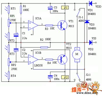
There are 2 kinds of solar automatic tracking controllers. One is Schmitt trigger light control composed of a light sensor and a Schmitt trigger or monostable trigger. The second one is usingtwo light sensors and two comparators to form two light-control motors and controlforeward and reversing. As throughout the year, the strength of the sun in the morning and at noon changes in ambient light, and the range is enormous, the above two controllersare difficult to make large solar energy receiver track in the sun-weather season. The control circuit described here also includes two voltage comparators. Butthe input side of the light sensors is composed of two photosensitive resistors connectedin series. (View)
View full Circuit Diagram | Comments | Reading(6447)
Excess temperature alarm circuit diagram
Published:2011/9/15 22:32:00 Author:Rebekka | Keyword: Excess temperature alarm
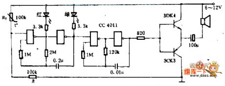
This circuitis composed ofa CMOS gate CC4011. It uses the ordinary thermistor for temperature measurement and it can emit sound, light and alarm. The two doors around the left side form the 2HZ controllable oscillator, and thetwo doors on the right formthe 400HZ controlled oscillator. When the temperature is normal, the partial-pressureof thermistor resistor RT and resistor R is lower than threshold voltage of NAND gate, two oscillators do not work. Once it is over temperature, RT is small enough, the first class NAND gate opens, the oscillator works, and the red and green light-emitting diodes alternating work, thenlthe oudspeaker emitssound. To save the transistor,it requires two tubes with the β> 150. (View)
View full Circuit Diagram | Comments | Reading(1284)
Low current anti-theft alarm circuit diagram
Published:2011/9/15 22:35:00 Author:Rebekka | Keyword: Low current anti-theft alarm
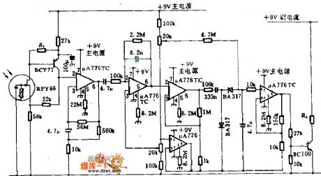
Detector RPY86 is produced by Mullard, and it only makes responses to the wavelength which isgreater than 6μm. It has not any response to thebackground light caused by sunlight and the sun. In order to gather infrared light onto the detector, it uses cheap mirror instead of Lens. μA776 is a programmable operational amplifier, and its bias current is only 300μA, which can be recharged by a small battery. Ra should be selected carefully, and the first operational amplifier's input voltage is 2 ~ 6V. Only when the thieves walk around the monitored area, the changes caused by the incident light will makethis circuit pull the alarm relay RL. (View)
View full Circuit Diagram | Comments | Reading(1609)
Flash alarm circuit diagram
Published:2011/9/15 22:36:00 Author:Rebekka | Keyword: Flash alarm
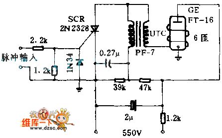
When people reach the safe or other metal objects, in order to get the photo of people, the sensor circuit will send a pulse to the warning circuit. Its positive edge will start work around semiconductor silicon-controlled rectifier and GE flash tube to drive the camera. (View)
View full Circuit Diagram | Comments | Reading(1114)
E-anesthetic circuit diagram
Published:2011/9/15 22:46:00 Author:Rebekka | Keyword: E-anesthetic
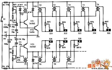
As shown is the electronic anesthesia circuit. The circuit can output 8 groups of electrode which output at the same time independently. Regulating any one of the groups, other groups will not be affected. You can choose the 2Hz ~ 50Hz frequency range. Generally taking 2 ~ 3Hz operating frequency will make 8-output cost 100mW power. Since the transistor oscillator is basically a constant current source, when 2 more groups output at the same time(such as 4 groups), if one group outputs high, the negative pulse output of other groups will be low. That means, they will influence each other. It is bad for E-anesthetic. So we should avoid this situation. To eliminate this shortcoming. We can add one Zener diode at both ends of the oscillator output transformer primary winding,. It play the role of limiting the regulator. (View)
View full Circuit Diagram | Comments | Reading(1755)
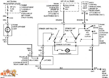
Cadillac luggage lock circuit diagram
Published:2011/9/15 2:20:00 Author:Rebekka | Keyword: Cadillac, Luggage lock
View full Circuit Diagram | Comments | Reading(731)
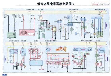
Chang an Star entire vehicle system circuit diagram
Published:2011/9/15 2:16:00 Author:Rebekka | Keyword: Chang an Star, entire vehicle system
View full Circuit Diagram | Comments | Reading(862)
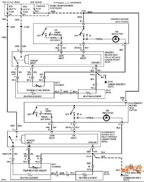
Cadillac heating seats circuit diagram
Published:2011/9/15 2:16:00 Author:Rebekka | Keyword: Cadillac, heating seats
View full Circuit Diagram | Comments | Reading(717)
| Pages:460/2234 At 20441442443444445446447448449450451452453454455456457458459460Under 20 |
Circuit Categories
power supply circuit
Amplifier Circuit
Basic Circuit
LED and Light Circuit
Sensor Circuit
Signal Processing
Electrical Equipment Circuit
Control Circuit
Remote Control Circuit
A/D-D/A Converter Circuit
Audio Circuit
Measuring and Test Circuit
Communication Circuit
Computer-Related Circuit
555 Circuit
Automotive Circuit
Repairing Circuit