
Circuit Diagram
Index 448
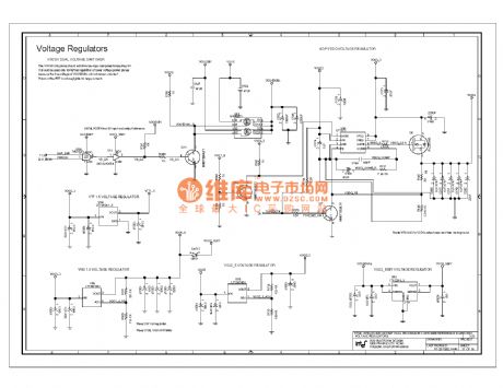
820e computer motherboard circuit diagram 68
Published:2011/10/23 20:44:00 Author:Ecco | Keyword: computer motherboard

View full Circuit Diagram | Comments | Reading(796)
845ddr computer motherboard circuit diagram 45
Published:2011/10/19 2:17:00 Author:Ecco | Keyword: computer motherboard
View full Circuit Diagram | Comments | Reading(796)
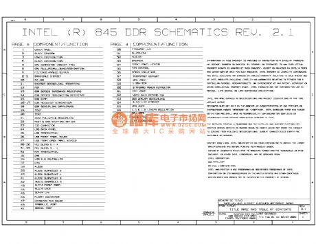
845ddr computer motherboard circuit diagram 43
Published:2011/10/19 2:31:00 Author:Ecco | Keyword: computer motherboard
View full Circuit Diagram | Comments | Reading(776)
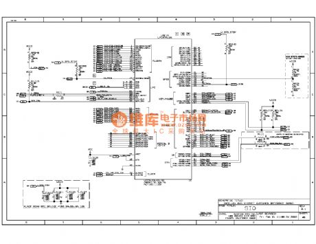
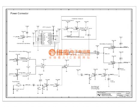
845ddr computer motherboard circuit diagram 04
Published:2011/10/23 20:30:00 Author:Ecco | Keyword: computer motherboard
View full Circuit Diagram | Comments | Reading(870)
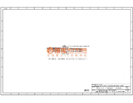
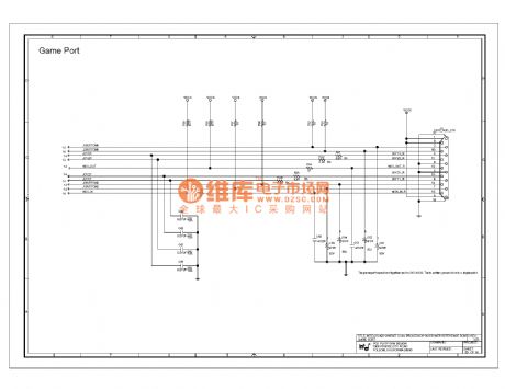
845ddr computer motherboard circuit diagram 03
Published:2011/10/23 20:38:00 Author:Ecco | Keyword: computer motherboard
View full Circuit Diagram | Comments | Reading(795)
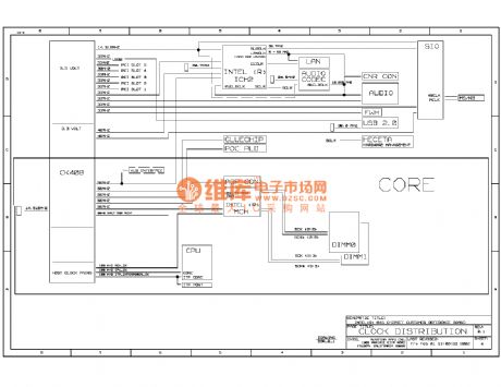
845ddr computer motherboard circuit diagram 02
Published:2011/10/23 20:38:00 Author:Ecco | Keyword: computer motherboard
View full Circuit Diagram | Comments | Reading(804)
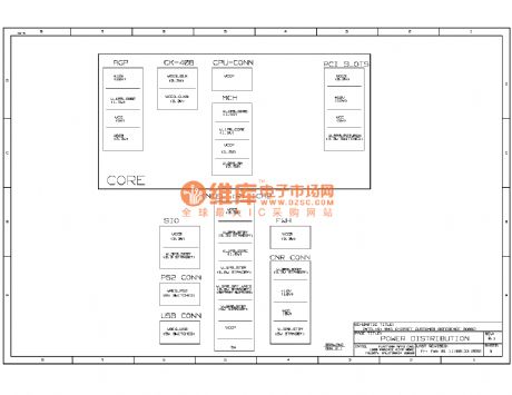
845ddr computer motherboard circuit diagram 01
Published:2011/10/23 20:37:00 Author:Ecco | Keyword: computer motherboard
View full Circuit Diagram | Comments | Reading(847)
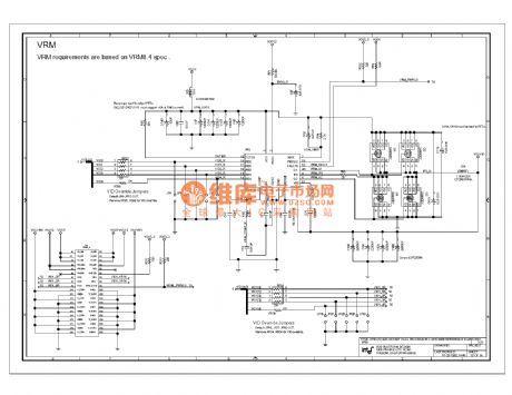
820e computer motherboard circuit diagram 73
Published:2011/10/23 20:47:00 Author:Ecco | Keyword: computer motherboard
View full Circuit Diagram | Comments | Reading(814)
820e computer motherboard circuit diagram 72
Published:2011/10/23 20:46:00 Author:Ecco | Keyword: computer motherboard

View full Circuit Diagram | Comments | Reading(841)
820e computer motherboard circuit diagram 69
Published:2011/10/23 20:44:00 Author:Ecco | Keyword: computer motherboard
View full Circuit Diagram | Comments | Reading(821)
820e computer motherboard circuit diagram 71
Published:2011/10/23 20:45:00 Author:Ecco | Keyword: computer motherboard
View full Circuit Diagram | Comments | Reading(851)
820e computer motherboard circuit diagram 70
Published:2011/10/23 20:45:00 Author:Ecco | Keyword: computer motherboard
View full Circuit Diagram | Comments | Reading(815)
Chang an Star multifunction rear wiper and jetter circuit diagram
Published:2011/10/20 22:18:00 Author:Rebekka | Keyword: Chang an Star , multifunction , rear wiper , jetter
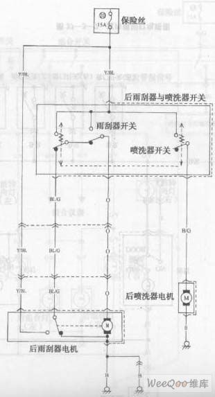
View full Circuit Diagram | Comments | Reading(708)
Chang an Star multi-purpose vehicle cooling system circuit diagram
Published:2011/10/20 2:34:00 Author:Rebekka | Keyword: Chang an Star, multi-purpose vehicle , cooling system
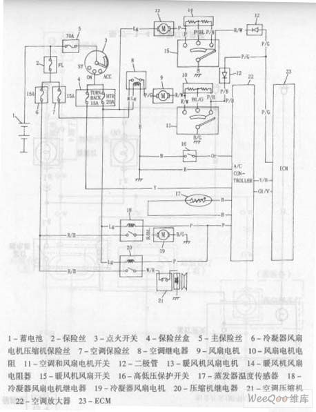
1. Battery 2. Fuse 3. Ignition switch 4. Fuse box 5. Main fuse 6. Condenser fan motor, compressor fuse 7. Air conditioning fuse 8. Air conditioning relay 9. Fan motor 10. Fan motor resistor 11. Air conditioning and fans the motor switch 12. diode 13. heater fan motor 14. heater fan resistor 15. heater fan switch 16. high and low pressure protection switch 17. evaporator temperature sensor 18. condenser fan motor relay 19. condenser fan motor 20. compressor relay 21. air conditioning compressor 22. Air conditioning amplifier 23.ECM (View)
View full Circuit Diagram | Comments | Reading(789)
Chang an Star multifunction vehicle ABS circuit diagram
Published:2011/10/20 2:34:00 Author:Rebekka | Keyword: Chang an Star, multifunction vehicle ABS
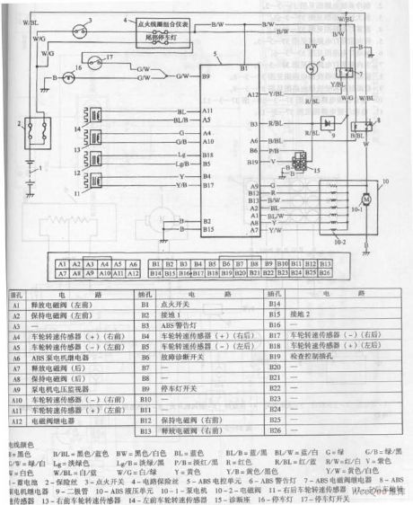
B-black B/BL-black/blue BW-black/white BL-blue BL/B-blue/black BL/W-blue/white G-green G/B-green/black G/W-green/white Lg-light green Lg/B-light green/balck P/B-Pink/black R-red R/BL-red/blue R/W-red/white V-purple W-white W/BL-white/blue W/G-white/green Y-yellow Y/B-yellow/black Y/W-yellow/black Y/W-yellow/black Y/W-yellow/white
1. Battery 2. Fuse 3. Ignition switch 4. 5.ABS electronic control circuit fuse unit 6.ABS warning lights 7.ABS solenoid valve relay 8.ABS pump motor relay 9. Diode 10.ABS hydraulic unit 10-1. Pump motor 10-2. Solenoid valve 11.Right rear wheel speed sensor 12. Left rear wheel speed sensor 13. The right front wheel speed sensor 14. The left front wheel speed sensor 15. Diagnostic Block 16. Stop lamps 17. Stop light switch (View)
View full Circuit Diagram | Comments | Reading(659)
Chang an Star SUV 6350C engine control system circuit diagram
Published:2011/10/20 2:34:00 Author:Rebekka | Keyword: Chang an Star SUV, engine control system
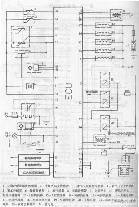
1. Air conditioning condenser temperature sensor 2. Coolant Temperature Sensor 3. Inlet air pressure and temperature sensors 4. Throttle position sensor 5. Hall sensor 6. Knock sensor 7. Oxygen sensor 8. Speed sensor 9. Air conditioning switch 10. Heater switch 11. Idle stepper motor 12-1. Gang injector 13-2. Gang injector 14-3. Gang injector 15-4. Gang injector 16. solenoid valve 17. Electric Fuel Pump 18. Fuel pump relay 19. Air conditioning relay 20. main relay 21. High-voltage ignition coil 23. Fault diagnosis socket 24. Accumulator
(View)
View full Circuit Diagram | Comments | Reading(1367)
Chang an Star SUV 6350B engine control system circuit diagram
Published:2011/10/20 2:33:00 Author:Rebekka | Keyword: Chang an Star SUV, engine control system

Changan Star SUV 6350B engine control system circuit diagram is shown as above.
1. Camshaft position sensor 2. Crankshaft position sensor 3. Intake manifold pressure sensor 4. Throttle position sensor 5. Engine coolant temperature sensor 6. Intake air temperature sensor 7.8. Empty 9. Oxygen sensor 10. Speed sensor 11 . heater switch 12.Air conditioning control module 13.Light switch 14.In light switch 16.Data transmission connector 17.ABS electronic control unit 18. Tachometer 20.2 19.No1 fuel injector 20. No 2 fuel injectors fuel injectors 22.4 21.No.3 No. 24-valve fuel injectors 23.EGR. Canister magnetic valve 24-1. Fuel pressure regulator vacuum switch valve 25. idle air control valve 26. radiator fan relay 27. radiator fan motor 28. diagnostic interface 29. pump relay 30. fuel pump 31. fault indicator 32. ignition coil assembly 33. ignition ring assembly 34. ignition switch 35. main relay 36. starter solenoid switch 37. accumulator 38. Engine Electronic Control Unit (View)
View full Circuit Diagram | Comments | Reading(1101)
Ceramic humidity sensor circuit diagram
Published:2011/10/20 2:32:00 Author:Rebekka | Keyword: Ceramic humidity sensor
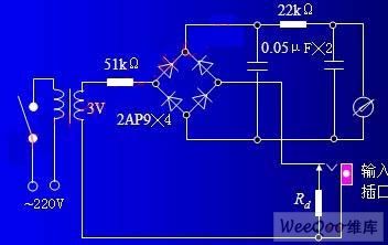
This circuit is suitable for high current ceramic humidity sensor. The wet circuit can get a strong signal, it can save the bridge and an amplifier. You can use electricity as power, as long as you choose the step-down transformer. The circuit isshown in Fig. (View)
View full Circuit Diagram | Comments | Reading(1235)
Magnetic reed, dryreed proximity switch sensor circuit diagram using CD4017
Published:2011/10/21 1:41:00 Author:Rebekka | Keyword: Magnetic reed, dryreed , proximity switch sensor
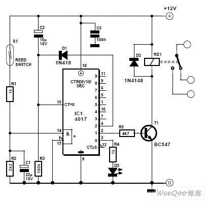
View full Circuit Diagram | Comments | Reading(6593)
Infrared remote control 5-speed motor speed controller circuit diagram
Published:2011/10/21 1:49:00 Author:Rebekka | Keyword: Infrared remote control, 5-speed motor speed controller
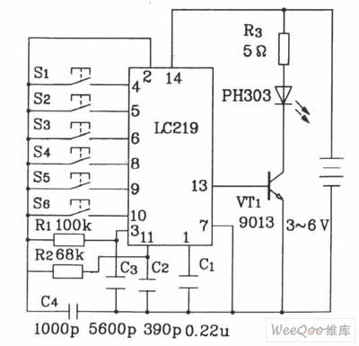
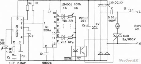
Infrared remote control 5-speed motor speed controller composed of LC219/220A has fewoutward turningcomponents. Its debugging is simple. The resonant frequency is 39kHz.
Infrared remote control 5-speed motor speed controller transmitter circuit composed of LC219.
Infrared remote control 5-speed motor speed controller receiver circuit composed of LC220A. (View)
View full Circuit Diagram | Comments | Reading(2750)
| Pages:448/2234 At 20441442443444445446447448449450451452453454455456457458459460Under 20 |
Circuit Categories
power supply circuit
Amplifier Circuit
Basic Circuit
LED and Light Circuit
Sensor Circuit
Signal Processing
Electrical Equipment Circuit
Control Circuit
Remote Control Circuit
A/D-D/A Converter Circuit
Audio Circuit
Measuring and Test Circuit
Communication Circuit
Computer-Related Circuit
555 Circuit
Automotive Circuit
Repairing Circuit