
Circuit Diagram
Index 452
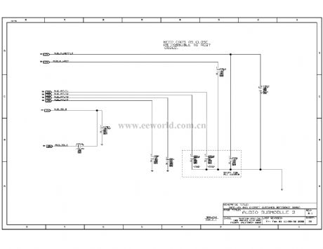
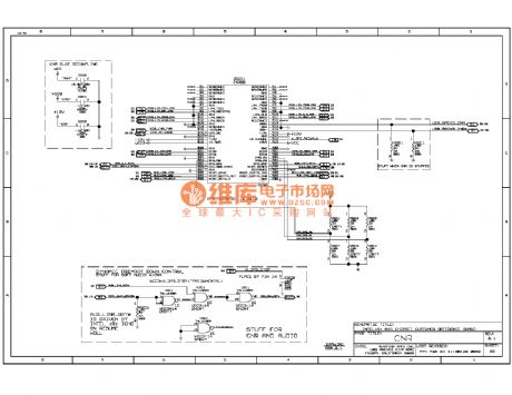
845ddr computer motherboard circuit diagram 39
Published:2011/10/19 2:28:00 Author:Ecco | Keyword: computer motherboard
View full Circuit Diagram | Comments | Reading(774)
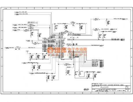
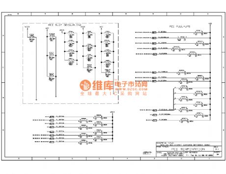
845ddr computer motherboard circuit diagram 38
Published:2011/10/19 2:27:00 Author:Ecco | Keyword: computer motherboard
View full Circuit Diagram | Comments | Reading(1306)
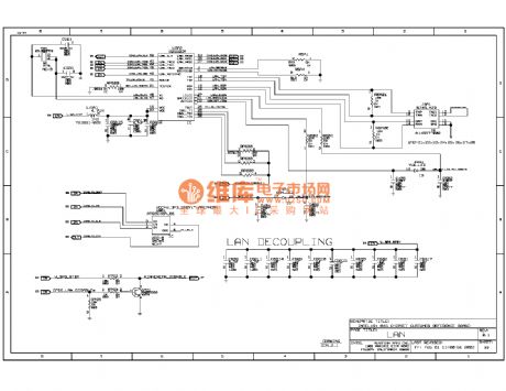
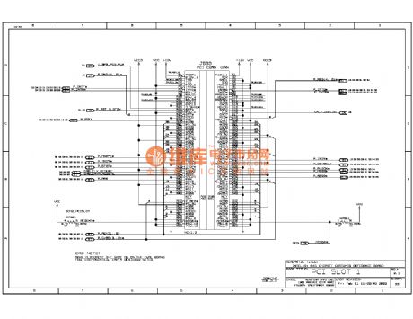
845ddr computer motherboard circuit diagram 37
Published:2011/10/20 2:36:00 Author:Ecco | Keyword: computer motherboard
View full Circuit Diagram | Comments | Reading(796)
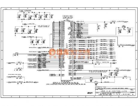
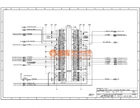
845ddr computer motherboard circuit diagram 36
Published:2011/10/20 2:43:00 Author:Ecco | Keyword: computer motherboard
View full Circuit Diagram | Comments | Reading(860)
845ddr computer motherboard circuit diagram 35
Published:2011/10/20 2:42:00 Author:Ecco | Keyword: computer motherboard
View full Circuit Diagram | Comments | Reading(945)
845ddr computer motherboard circuit diagram 34
Published:2011/10/20 2:41:00 Author:Ecco | Keyword: computer motherboard
View full Circuit Diagram | Comments | Reading(874)
845ddr computer motherboard circuit diagram 33
Published:2011/10/20 2:41:00 Author:Ecco | Keyword: computer motherboard
View full Circuit Diagram | Comments | Reading(776)
845ddr computer motherboard circuit diagram 32
Published:2011/10/20 2:40:00 Author:Ecco | Keyword: computer motherboard
View full Circuit Diagram | Comments | Reading(893)
Internal circuit structure of HN911 module
Published:2011/9/27 2:02:00 Author:Rebekka | Keyword: internal circuit structure

HN911 series modules use new technology and new technology. The module circuit is composedof the high sensitivity of pyroelectric infrared sensors, amplifiers, signal processing and output circuit. Its output terminal connects with transistor amplifier or one-shot circuitto drive relay. It connects to the optical coupling circuit to drive the triac. (View)
View full Circuit Diagram | Comments | Reading(798)
BTH801F and BTH801J infrared remote control transmitter and receiver module applications circuit diagram
Published:2011/9/27 2:01:00 Author:Rebekka | Keyword: Infrared remote control, transmitter and receiver
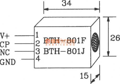
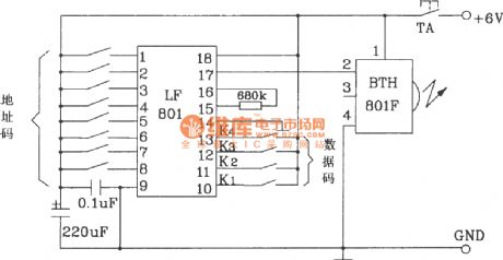
BTH-801F/BTH-801J is the new infrared remote control transmitter / receiver-specific modules. Paired two modules can easily constitute an infrared remote control transmitter / receiver circuit. It is suitable for infrared remote control switches, alarm and many other fields.
BTH-801F/BTH-801J shape pin map.
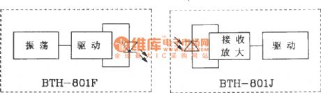
BTH-801F/BTH-801J internal block diagram.
The main electrical parameters of BTH-801F/BTH-801J infrared transmitter / receiver module are as follows: Supply voltage is 4 ~ 8V; Transmitter module operating current is greater than 20mA; Receiver module operating current is less than 3mA; The operation frequency is adjustable within 3060kHz, typical value is 40kHz; Temperature is 18 ~ +60 ℃, storage emperature is 25 ~ +90 ℃; Working distance is 5 ~ lOm.
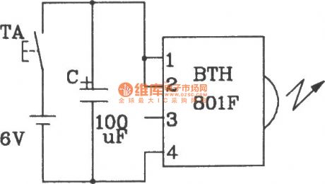
Single infrared remote control transmitter circuit composed of BTH-801F.
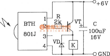
Single infrared remote control receiver circuit composd of BTH-801H.
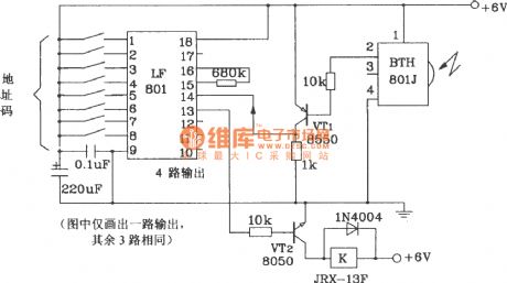
Multi-channel infrared remote control transmitter circuit composed of BTH-801F.
Multi-channel infrared remote control receiver circuit composed ofBTH-801J.
(View)
View full Circuit Diagram | Comments | Reading(2239)
Remote electric fan circuit diagram
Published:2011/9/26 22:38:00 Author:Rebekka | Keyword: Remote electric fan
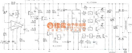
The circuit includes infrared receiver demodulation circuit, three-block speed control circuit and simulated natural wind circuit. (View)
View full Circuit Diagram | Comments | Reading(2707)
Novel infrared remote control switch circuit diagram
Published:2011/9/26 22:33:00 Author:Rebekka | Keyword: Novel infrared remote control switch
Infrared remote controlling devide is convenient and practical as the advantages of small size, low power consumption, powerful, low cost, and it is especially used in the technology commonly household appliances. In the high pressure, irradiation, toxic gases, dust and other industrial environments with infrared remote control, it is not only safe but also effectively to isolate electromagnetic interference. The circuit shows the new infrared remote control switch circuit. TVs, VCRs, air conditioners and other infrared remote control transmitter signals are pulse code modulation signal, the difference is that instruction encoding format, the signal carrier frequency is different from where we do not concern about the specific encoding instructions. (View)
View full Circuit Diagram | Comments | Reading(1500)
Five way four-function infrared remote control circuit diagram
Published:2011/9/26 22:27:00 Author:Rebekka | Keyword: infrared remote control
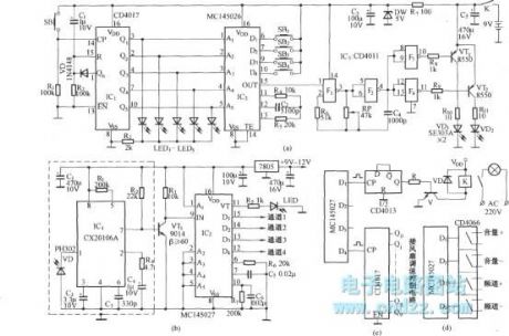
The circuit is translated and edited by MC145026. (a) figure is the remote control transmitter (b) plan is the infrared receiver and decoding circuit (c) Figure shows the controllingcontent which can be connected to each data outputend. (d) graph shows the circuit which the four data ports of MC145027topass four analog switch circuit CD4066and control the volume of an audio amplifier and speakers.
(View)
View full Circuit Diagram | Comments | Reading(2926)
Object motion detector circuit diagram
Published:2011/9/26 22:20:00 Author:Rebekka | Keyword: Object motion detector
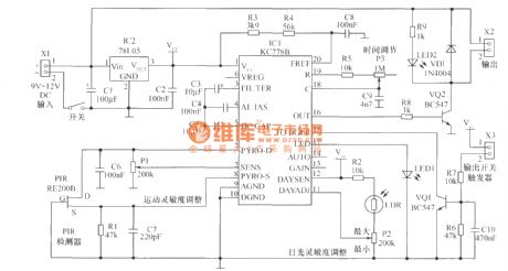
The heart of the motion detector movement detection circuit is motion detection chip IC1 (KC778B). The signal frequency from PIR sensor is low (0.1Hz ~ 10Hz) while the band is very wide, the chip will optimize it. The working voltage of KC778B is 4V ~ 15V, 78L05 requires 9V ~ 12V input voltage. The circuit has three sensitivity controllers. You can see a brief description in the figure. The detection sensitivity is cotrolled by the semi-variable resistor P1 connecting on chip 2 feet. When the level of the pin is connected to the sensor, thepotential is equal to the potential on pin 7(about 0.5V),and thesensitivity is the lowest. When pin 2 is grounded (about 0.125V), system sensitivity is the maximum. Sun sensitivity is controlled by semi-variable resistor and P2 photodiode LDR. Generally we hope that this detector does not work in the daytime, but only work at night, and itmay be connected to the lighting line. If you do not need this feature, you can connect Vcc pin on 12 feet and 11 feet will be vacant. P3 is adjusted by the timing pulse, the output pulse width in the range is more than 1.5s. (View)
View full Circuit Diagram | Comments | Reading(3564)
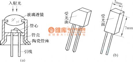
The structure of photodiode
Published:2011/9/26 22:16:00 Author:Rebekka | Keyword: photodiode, structure
View full Circuit Diagram | Comments | Reading(682)
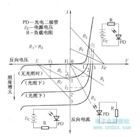
Volt-ampere characteristic curve of photodiode
Published:2011/9/26 22:16:00 Author:Rebekka | Keyword: Volt-ampere characteristic curve , photodiode
View full Circuit Diagram | Comments | Reading(2329)
Infrared alarm switch circuit diagram
Published:2011/9/26 22:15:00 Author:Rebekka | Keyword: Infrared alarm switch
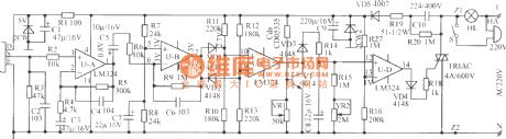
The figure shows the infrared alarm switch circuit. It uses the most popular domestic and international human pyroelectric PIR sensor as the signal detector. It has a high sensitivity, the detection range is up to 10m or more, the depression angles is up to 86 degrees, horizontal viewing angle is up to 120o. It is only sensitive to the specific wavelength infrared light that released by human body, so it has a minimal malfunction. When someone walks in the detection region in 0.3Hz ~ 3Hz frequency. It can give birth to weak signal sense. It is amplified by the UA, UB two-stage and outputs strong signal of 0.5V ~ 5.5V from the U-B7 feet. VD1, VD2, R10 ~ R13 and UC form the threshold comparator. The signal voltage induced by PIR can be positive or negative, so the U-B7 pin outputs voltage can be positive or negative (in terms of center voltage 3V). When the voltage on C8 is less than 13 feet (1V), the pin 14 has no output. Thyristor turns off, the lights automatically turn off. People sleep at night or when there is no one at home, you can turn off the switch S. If there is a thief sneaked into the detection region, the lights will be accompanied by ringing. It can scare away the thief, played the role of security. (View)
View full Circuit Diagram | Comments | Reading(3180)
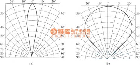
The directional property curve of infrared light-emitting diode
Published:2011/9/16 1:17:00 Author:Rebekka | Keyword: infrared light-emitting diode, directional property curve
View full Circuit Diagram | Comments | Reading(918)
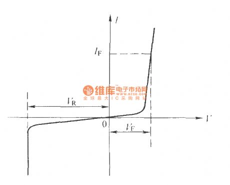
The volt-ampere characteristic curve of infared light-emitting diode
Published:2011/9/16 1:16:00 Author:Rebekka | Keyword: volt-ampere characteristic curve , infared light-emitting diode
View full Circuit Diagram | Comments | Reading(2303)
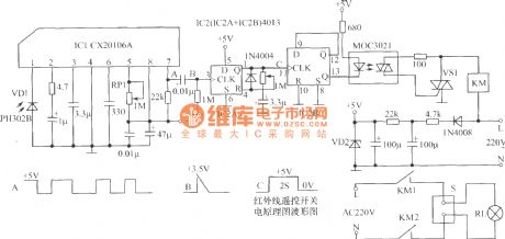
Infrared delay light switch circuit diagram
Published:2011/9/27 1:33:00 Author:Rebekka | Keyword: Infrared delay light switch
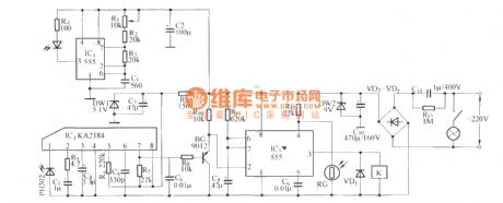
KA2184 infrared receiver integrated circuit ismade in the Korean. The performance, parameters and pin functions are identical with the CX20106.They can be directly used interchangeably. Since the circuit uses infrared reflective circuit structure. So infrared transmitter and receiver need to be installed in the same direction and in the same plane. It makes the transmitter and the receiver become integrated structure, and they use the same power supply. This work style also happens to meet the circuit standard. Such as long-term, short work of working state. In this circuit, it uses multivibrator composed of the NE555 as infrared emission tube drive circuit. (View)
View full Circuit Diagram | Comments | Reading(1313)
| Pages:452/2234 At 20441442443444445446447448449450451452453454455456457458459460Under 20 |
Circuit Categories
power supply circuit
Amplifier Circuit
Basic Circuit
LED and Light Circuit
Sensor Circuit
Signal Processing
Electrical Equipment Circuit
Control Circuit
Remote Control Circuit
A/D-D/A Converter Circuit
Audio Circuit
Measuring and Test Circuit
Communication Circuit
Computer-Related Circuit
555 Circuit
Automotive Circuit
Repairing Circuit