
Magnetic Sensor
Index
Unipolar mode temperature compensation circuit with linear output integrated magnetic field sensor AD22151
Published:2012/10/7 21:28:00 Author:Ecco | Keyword: Unipolar mode, temperature compensation, linear output , integrated, magnetic field sensor
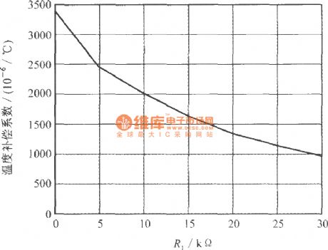
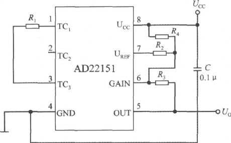
The feature is that R1 is connected between the TC1 end and TC3 end, so that the potential of magnetic null point is not equal to UCC / 2 to compensate for the high temperature coefficient below -2000 × 10-6/ ℃. When TC2 end is open, the compensating resistor R1 and internal resistor RB form the temperature compensation coefficient voltage divider. Under unipolar mode, the relationship curve between R1 resistance value and temperature compensation coefficient is shown as below.
(View)
View full Circuit Diagram | Comments | Reading(2162)
camera electronic metering system
Published:2011/9/6 23:34:00 Author:chopper | Keyword: camera, electronic metering system
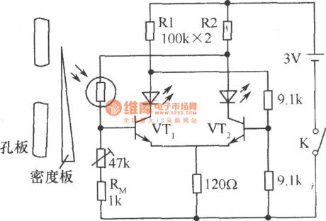
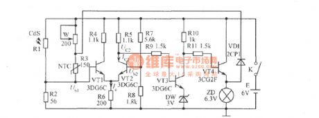
In the midrange camera, CdSphotosensitive resistor is taken as electronic metering device. Light is on the CdSphotosensitive resistorthrough the orifice, and you can move thedensity plate, so that the circuit will achieve a balance, and then two LEDs will light evenly to express the proper exposure.If only onelights while the other does not, it is due to underexposure or over exposure, then moving the density board can achieve the correct exposure purpose.The thermistor RM in the circuit(1kΩ) has temperature compensation function, to compensate error for temperature changes caused by photosensitive resistor. (View)
View full Circuit Diagram | Comments | Reading(1412)
timing battery-conserving switch
Published:2011/9/6 23:34:00 Author:chopper | Keyword: timing, battery-conserving switch
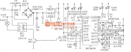
Door lamp isusually controlled by hands,which may make some waste of electrical energy and inconvenience if someone forgets to turn on or turn off.If it can increase light control and timing functions,it can achieve automation and energy-saving effect.The ready-made light-controlled timing ICMG2001B is a cheap 1h-36h,nine-gear optional timing,delay IC,and its peripheral circuit is simple ,and it is with driver of indicator light as well as interface of photoresistor.It adopts cheap 32.768kHz crystal as clock source whose order of accuracy will reach one over one hundred thousand.So it is suitable for automatical control circuit of street lamp. (View)
View full Circuit Diagram | Comments | Reading(1289)
delay energy-saving lamp circuit
Published:2011/9/6 23:33:00 Author:chopper | Keyword: delay, energy-saving lamp
The delay energy-saving lamp shown in the picture is a acousto-optic dual control power-saving delay lamp.It can directly replace ordinary lighting switch without changing the existing lighting circuit and can also control the light bulb not to shine during the day or under strong light even there is a big sound, and it will turn on automatically in the evening or under low light when it encounters some sound (such as voice, footstep, etc.)and it can turn off automatically after about 30s (time can be set).It is suitable for stairs, corridors and other places that just need short lighting. (View)
View full Circuit Diagram | Comments | Reading(1884)
electronic greeting card circuit
Published:2011/9/6 23:25:00 Author:chopper | Keyword: electronic, greeting card
View full Circuit Diagram | Comments | Reading(1758)
long time delay light-operated switch
Published:2011/9/6 23:28:00 Author:chopper | Keyword: delay, light-operated switch
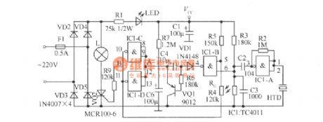
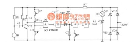
Figure shows the improved sound and light control switch, and its delay time can extend to 3min or so, which can meet the requirements of users well.If you want to continue to extend the dely time when in use,you can clap(make some sound) again when the light bulb is bright,which is more convenient to use.Components selection:IC1 should use dual-input four NAND-gate TC4011. RG is the photoresistance,and its effect is better if the difference between its light resistance and dark resistance is greater.Resistor adopts 1/8W carbon film resistors. (View)
View full Circuit Diagram | Comments | Reading(1737)
object motion path distinguishmen circuit
Published:2011/9/6 23:44:00 Author:chopper | Keyword: motion path, distinguishmen circuit
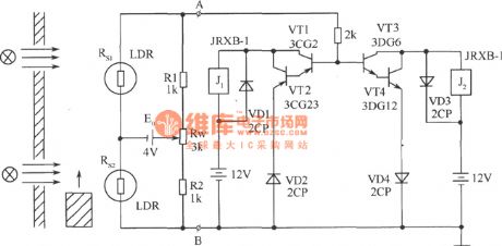
Puttwo photoresistors who have the similar resistance and performance on the same side of the object motion path at theappropriate distance.Settwo light sourceson the relative position of the other side respectively, so that objects can move in a straight line between the light source and photosensitive resistor. Using the circuit shown in picturecan determine the direction of motion path. Circuit is formed by the bridge and polarity distinguishment. Rs1, Rs2, R1, R2, and Rw form the bridge and power supply E0 offers the power,and endsA, B output. (View)
View full Circuit Diagram | Comments | Reading(1532)
precise optical control circuit
Published:2011/8/25 20:54:00 Author:chopper | Keyword: optical, control circuit
The circuit shown in the picture is a precise optical control circuit, and its work is noteffected by supply voltage and ambient temperature. Resistors R1, R2, R6 andphotosensitive resistor R5 form thetwo bridge of Wheatstone bridge together. (View)
View full Circuit Diagram | Comments | Reading(1497)
simple light-controlled switch
Published:2011/8/28 4:24:00 Author:chopper | Keyword: simple, light-controlled switch
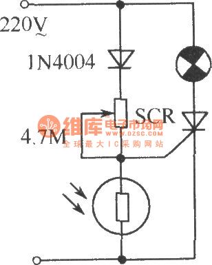
As shown,it is a simple light-controlled switch. In some public places such as corridor, street lightthere are automatical light-controlled switches, which is not only convenient but also saving energy. It will automatically turn on in the dark,and turn offautomatically when it is light.Adjustable 4.7MΩ potentiometeris applicable to different types of photosensitive resistors and can light under certain conditions (dark level). (View)
View full Circuit Diagram | Comments | Reading(1932)
Homemade photoelectric coupler
Published:2011/9/2 23:24:00 Author:chopper | Keyword: Homemade, photoelectric coupler
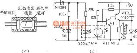
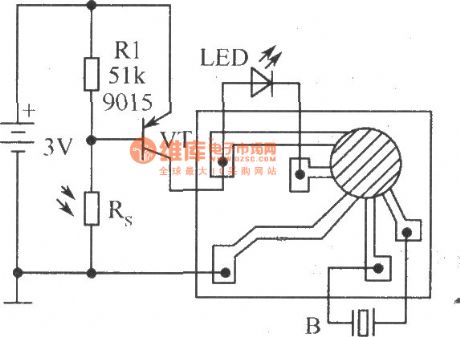
Combine the Φ55mm red LED andphotosensitive resistorby transparent tape and put them into a color pen-holder (black is good),then seal the two ends with glue, and it becomes an photoelectric coupler, which is applied for low-frequency switching circuit,just as shown in Figure (a) . Figure (b) is a outage alarm circuit made by photoelectric coupler, which can send an alarm when the power fails.When the power is available,the red LED of the photoelectric coupler is bright and the resistance of thephotosensitive resistor will decrease after coupling,then VT1 stops,and the oscillator formed by VT1,VT2 does not run. (View)
View full Circuit Diagram | Comments | Reading(1319)
bridge type photoelectric detector formed by photosensitive resistor
Published:2011/9/2 23:22:00 Author:chopper | Keyword: bridge type, photoelectric detector, photosensitive resistor
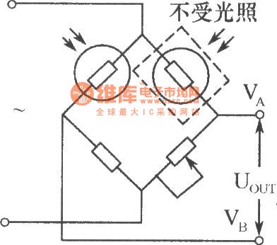
In the industrial photoelectric measuring device, the photosensitive resistor can form the bridge type photoelectric detector, which is shown in the picture. Two same model (darkness resistance equivalent)photosensitive resistors are used as the bridge arms, one for photoelectric detection, and the other sealed with black tape to avoid light for temperature compensation.This bridge type photoelectric detector can adopt the DC or AC. When using AC modulation, it outputs AC signals to reduced null drift of the amplifier. (View)
View full Circuit Diagram | Comments | Reading(1371)
Light automatic regulator circuit
Published:2011/8/28 4:19:00 Author:chopper | Keyword: Light, automatic regulator
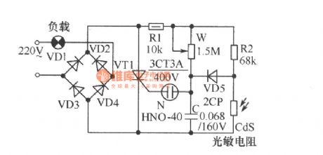
As shown, the circuit can adjust light level according to the strength of outside light automatically. If the external brightness is high, light will be dark, whereas the brightness is low, light will be bright. The thyristor VT1 and diodes VD1~VD4 in figure form full-wave phased circuit with the neontube N as trigger tube of VT1.AdjustingW canchange the charging time constant of capacitor C, that is to change the conduction angle of VT1, in order to control the brightness of the light. (View)
View full Circuit Diagram | Comments | Reading(1471)
Beam blocking alarm
Published:2011/8/25 20:50:00 Author:chopper | Keyword: Beam, blocking alarm
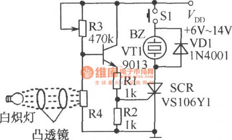
As shown,when the photosensitive resistor R4 is under light, its resistance is small, so the transistor VT1 and unidirectional thyristor SCR are closed; when the beam is blocked, base voltage of VT1rises, and VT1, SCR is conductive, and buzzer BZ will have the power and send an alarm. S1 is the reset switch. When S1 is pressed, the circuit stops the alarm.
(View)
View full Circuit Diagram | Comments | Reading(1201)
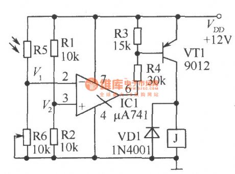
precise optical and black control circuit
Published:2011/8/25 20:46:00 Author:chopper | Keyword: precise, optical and black, control circuit
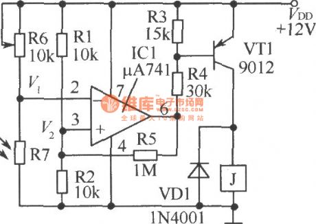
The precise optical and black control circuit is shown as picture. Sinceittakes some positive feedback through R5, changes will be slight behind the actionif the light changes, in order to avoid the frequent jitterof relay when light intensityis on the critical state. (View)
View full Circuit Diagram | Comments | Reading(1307)
photorelay
Published:2011/8/25 20:39:00 Author:chopper | Keyword: photorelay
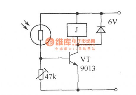
If you use the photosensitive resistoras the optical switch circuit,its sensitivity is very high.The picture shows the photorelay.When the light is low, VT does not turn on; when there is a certain intensity of light exposure, the resistance ofphotosensitive resistor will get small, and VT will get sufficient base current and get conducted, resulting in a larger collector current, and the relay will close. (View)
View full Circuit Diagram | Comments | Reading(1098)
the principle of gas stove flameout alarm
Published:2011/8/19 7:02:00 Author: | Keyword: principle, gas stove, flameout alarm

It is very dangerous if the gas stove is out and nobody finds it.Although thetop gas stoveis with automatic flameout control and protection device, the price is too high to spread. The gas stove flameout alarm shown in the picture can monitor the stove and send out the alarm.Core component is LM324 quad op-amp.IC1-1 is a comparator, IC1-2 is a follower; R4, R5 are the photosensitive resistors, the resistance changes with light intensity; AN is a reset switch for discharging the electric charge of capacitors C1, C2. (View)
View full Circuit Diagram | Comments | Reading(1292)
Electronic candles circuit
Published:2011/8/16 2:11:00 Author: | Keyword: Electronic candles
View full Circuit Diagram | Comments | Reading(1314)
photoelectric controlled electrical socket circuit
Published:2011/8/14 1:26:00 Author:chopper | Keyword: photoelectric controlled, electrical socket
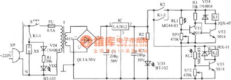
This device adopts ordinary flashlight as remote command,and makes a controlled electrical socket.It can control the power state of electrical socket by pressing the flashlight switch within a few meters,so it is easy to use.IC can be replaced by AN7812,LM7812,W7812 and other models.The current amplification factor β of VT1~VT3 is about 200. RL1 and RL2 use MG44-03 plastic resin encapsulated photosensitive resistors,as well as other ordinary photosensitive resistors whose light photosensitive resistance≤ 5kΩ, dark photosensitive resistance ≥ 1MΩ resistor instead of the . T is the 8W~10W power transformer. (View)
View full Circuit Diagram | Comments | Reading(1273)
application circuit when the TC-3330 monolithic integrated photoelectric switch drives different loads
Published:2011/8/14 1:15:00 Author:chopper | Keyword: application circuit, monolithic, integrated, photoelectric switch, different loads
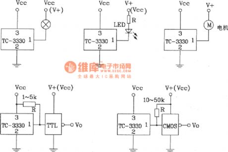
When the TC-3330 monolithic integrated photoelectric switch drives different loads,its application circuit TC-3330 can also be usedon bar code identification,tension sensing, optical cable isolator, paper or object detection, counting, speed measurement and other fields.The photocoupler made by it (diode output type, transistor output type, Darlington type) has excellent performance, high reliability,and wide range of applications. (View)
View full Circuit Diagram | Comments | Reading(1371)
light-controlled timer switch circuit
Published:2011/8/20 3:56:00 Author: | Keyword: light-controlled, timer switch
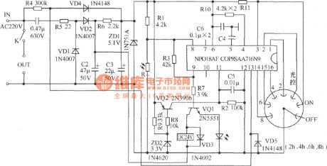
The picture shows a Mexican light-controlled timer switch circuit, which is suitable for outdoor street lamp and the supply control of advertising lamp box. It is a product that combines the light control function as well as gear shift and timing,and the circuit is simple,easy to make.Set the rotary switch at timing gear 2h, 4h, 6h or 8h,and this circuit will supply the correspondingcontrol time automatically when it has no light to save energy and reduce invalid energy. (View)
View full Circuit Diagram | Comments | Reading(1668)
| Pages:1/3 123 |
Circuit Categories
power supply circuit
Amplifier Circuit
Basic Circuit
LED and Light Circuit
Sensor Circuit
Signal Processing
Electrical Equipment Circuit
Control Circuit
Remote Control Circuit
A/D-D/A Converter Circuit
Audio Circuit
Measuring and Test Circuit
Communication Circuit
Computer-Related Circuit
555 Circuit
Automotive Circuit
Repairing Circuit