
Index 155
REMOTE_AMPLIFIER
Published:2009/6/24 3:51:00 Author:Jessie
View full Circuit Diagram | Comments | Reading(686)
TELEPHONE_RING_AMPLIFIER
Published:2009/6/24 3:41:00 Author:May
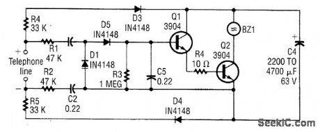
This circuit takes its operating power from the telephone line BZ1 is a piezoelectric transducer. (View)
View full Circuit Diagram | Comments | Reading(606)
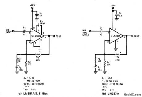
TRANSFORME_RLESS_BALANCE_INPUTS_MICROPHONE_PREAMP
Published:2009/6/24 3:39:00 Author:May
View full Circuit Diagram | Comments | Reading(1456)
ONE_SHOT_MULTIVIBRATOR
Published:2009/6/24 3:49:00 Author:Jessie
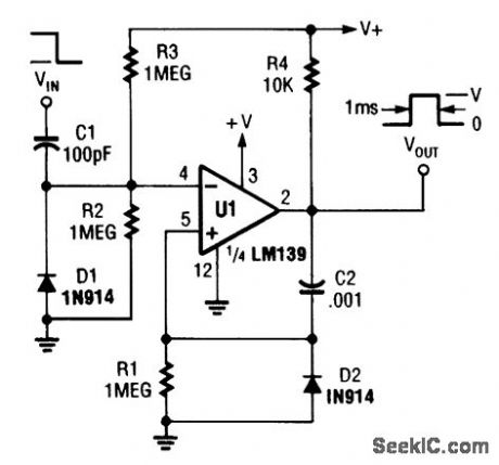
An LM139 section can be used as a one shot (View)
View full Circuit Diagram | Comments | Reading(2428)
LM382_PHONO_PREAMPLIFIER_RIAA
Published:2009/6/24 3:47:00 Author:Jessie
View full Circuit Diagram | Comments | Reading(905)
ULTRA_HIGH_GAIN_AUDIO_AMPLIFIER
Published:2009/6/24 3:33:00 Author:May
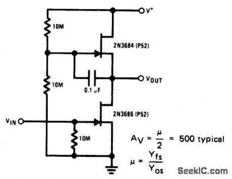
Sometimes called the JFET μt-amp, this circuit provides a very low power, high gain amplifying function. Since pt of a JFET in-creases as drain current decreases, the lower drain current is, the more gain you get. Input dynamic range is sacrificed with increasing gain, however. (View)
View full Circuit Diagram | Comments | Reading(2761)
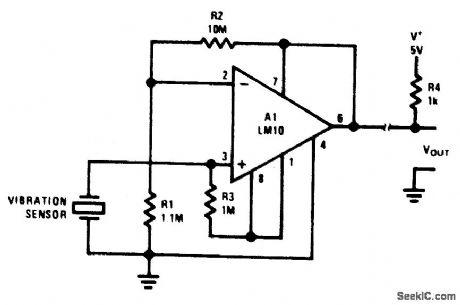
TRANSDUCER_AMPLIFIER
Published:2009/6/24 3:31:00 Author:May
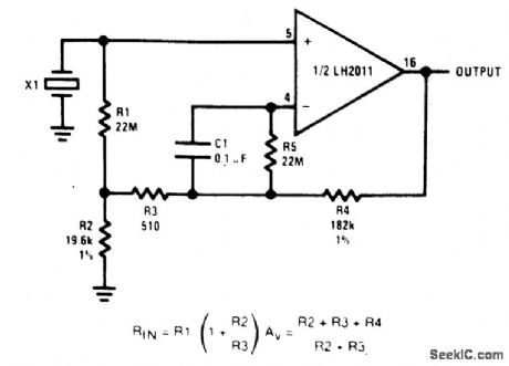
This circuit is high-input-impedance acamplifier for a piezoelectric transducer. Input resistance is 880 M, and again of 10 isobtained. (View)
View full Circuit Diagram | Comments | Reading(843)
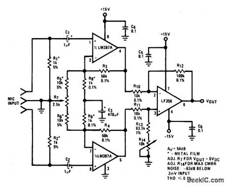
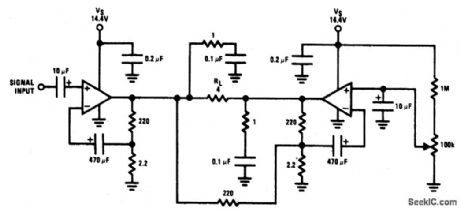
ELECTRONIC_BALANCED_INPUT_MICROPHONE_AMPLIFIER
Published:2009/6/24 3:30:00 Author:May
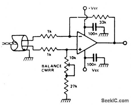
It is possible to simulate the balanced per-formance of a transformer electronically with a different amplifier. By adjusting the presets, the resistor ratio can be balanced so that the best CMRR is obtained. It is possible to get a better CMRR than from a transformer. Use a RC4136 which is a quad low noise op amp. (View)
View full Circuit Diagram | Comments | Reading(954)
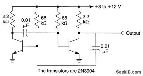
BASIC_TRANSISTOR_AMPLIFIER_CIRCUITS
Published:2009/6/24 3:29:00 Author:May
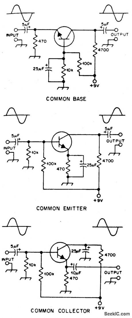
Typical component values are given for use at audio frequencies, where these circuits are used most often. The input and output phase relationships are shown. (View)
View full Circuit Diagram | Comments | Reading(747)
TRANSFORMERLESS_MICROPHONE_PREAMPS_UNBALANCED_INPUTS
Published:2009/6/24 3:40:00 Author:Jessie
View full Circuit Diagram | Comments | Reading(658)
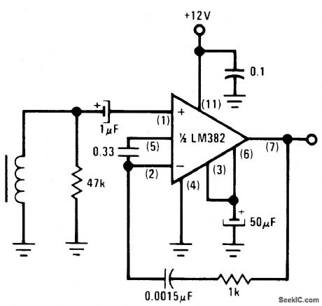
GENERAL_PURPOSE_PREAMPLIFIER
Published:2009/6/24 3:28:00 Author:May
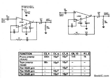
Not much can be said about how the LM382 works as most of the circuitry is contained within the IC. Most of the frequency-determining components are on the chip-only the capacitors are mounted externally. The LM382 has the convenient characteristic of rejecting ripple on the supply line by about 100 dB, thus greatly reducing the quality requirment for the power supply. (View)
View full Circuit Diagram | Comments | Reading(2893)
ASTABLE_MULTIVIBRATOR_WITH_STARTING_NETWORK
Published:2009/6/24 3:35:00 Author:Jessie
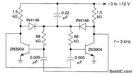
This circuit will start with a slowly rising supply voltage waveform. (View)
View full Circuit Diagram | Comments | Reading(0)
MICROPHONE_AMPLIFIER
Published:2009/6/24 3:34:00 Author:Jessie
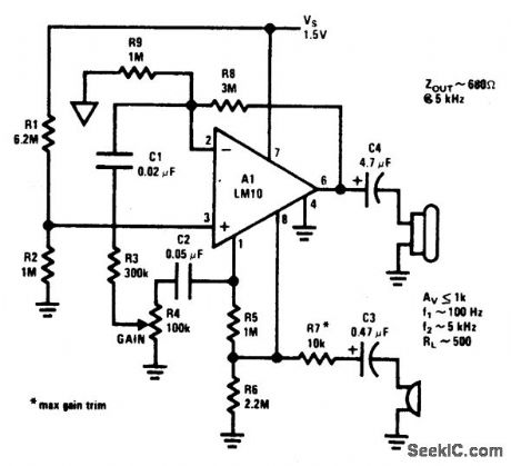
This circuit operates a 1.5 Vdc from source. (View)
View full Circuit Diagram | Comments | Reading(939)
HIGH_SLEW_RATE_POWER_OP_AMP_AUDIO_AMP
Published:2009/6/24 3:24:00 Author:May
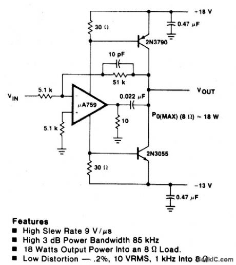
View full Circuit Diagram | Comments | Reading(1295)
RADON_MONITOR_AMPLIFIER_AND_HEAD
Published:2009/6/24 3:27:00 Author:Jessie
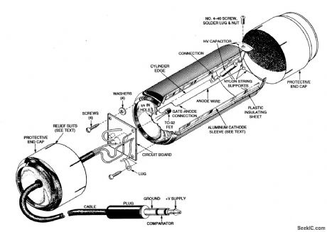
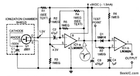
A positively charged anode wire attracts electrons and a negatively charged cathode attracts positively charged ions. The recombination of electrons and ions causes a current that produces a voltage pulse. The cathode is maintained at -500 V by a charge on the 0.1-μF capacitor.A beverage can forms the chamber, an aluminum can forms the cathode, and half cans form protective end covers. The amplifier circuit board is shown to the left of center. (View)
View full Circuit Diagram | Comments | Reading(1106)
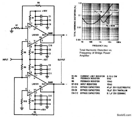
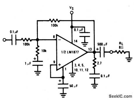
16_W_BRIDGE_AMPLIFIER
Published:2009/6/24 3:25:00 Author:Jessie
View full Circuit Diagram | Comments | Reading(0)
PHONO_AMPLIFIER
Published:2009/6/24 3:22:00 Author:May
Used when maximum input impedanceis required or the signal attenuation of the voltage divider volume controlis undesirable. (View)
View full Circuit Diagram | Comments | Reading(672)
BRIDGE_AUDIO_POWER_AMPLIFIER
Published:2009/6/24 3:21:00 Author:May
View full Circuit Diagram | Comments | Reading(656)
INVERTING_UNITY_GAIN_AMPLIFIER
Published:2009/6/24 3:19:00 Author:May
View full Circuit Diagram | Comments | Reading(617)
SINGLE_OP_AMP_FULL_WAVE_RECTIFIER
Published:2009/6/24 3:19:00 Author:May
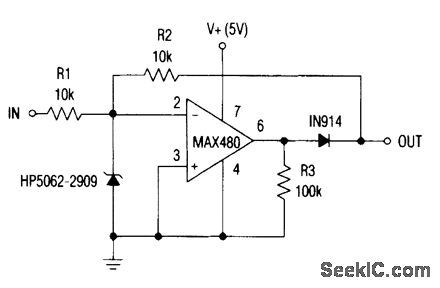
This circuit operates from +5 V and uses a single op amp to deliver a full-wave rectified output of the input signal. (View)
View full Circuit Diagram | Comments | Reading(1297)
| Pages:155/250 At 20141142143144145146147148149150151152153154155156157158159160Under 20 |
Circuit Categories
power supply circuit
Amplifier Circuit
Basic Circuit
LED and Light Circuit
Sensor Circuit
Signal Processing
Electrical Equipment Circuit
Control Circuit
Remote Control Circuit
A/D-D/A Converter Circuit
Audio Circuit
Measuring and Test Circuit
Communication Circuit
Computer-Related Circuit
555 Circuit
Automotive Circuit
Repairing Circuit