
Mixer
Index 2
SIMPLE_MIXER
Published:2009/7/8 4:26:00 Author:May
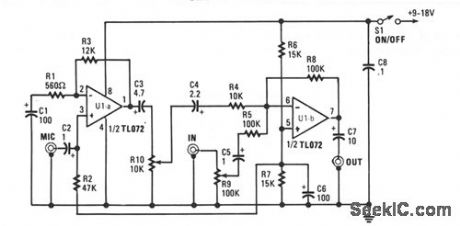
This mixer is built around a TL072 dual BiBET op anp with a JFET input stage,and can be powered from a single-ended 9-to 18-V power surry.The microphone input is capacitively coupled to the noninverting input of U1a.
Resistors R1 and R3 set the voltage gain at about 26 dB and serve as a negative feedback network for U1a.Capacitors C1 through C3 are dc-blocking capacitors.Most high-impedance microphones have outputs of a few mV.Often,a preamp stage just isn't enough,so the microphone signal is given a boost of about 20 db in the mixer.The noninverting input of U1b is biased to half the surry voltage by R6,R7,and C6.Rsistors R5 and R8 make up the negative-feedback network and set the voltage gain of U1b at unity.Capacitor C5 is for dc blocking at this input. (View)
View full Circuit Diagram | Comments | Reading(656)
BROADBAND_MIXER
Published:2009/7/7 23:36:00 Author:May
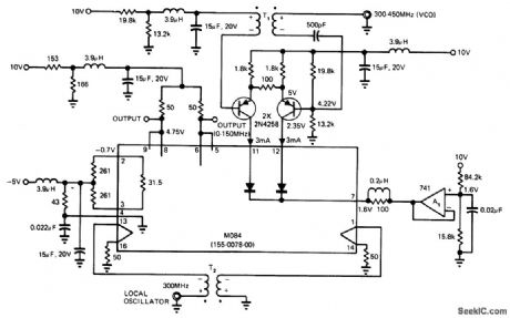
Uses Tektronix M084 multiplier as broadband mixer having linear output within -3 dB limit from 2 MHz to above150 MHz. Current-gain cell in multiplier takes advantage of logarithmic relationship between current and voltage in a semiconductor. Output function includes product of two Input signals,a300-450MHz swept VCO signal and a 300-MHz local oscillator signal.-M .Jaffe, Build a Low Cost Wideband Mixer with a Monolithic Multiplier, EDN Magazine. May 20,1975,p63-64. (View)
View full Circuit Diagram | Comments | Reading(1237)
MICROPHONE_MIXER
Published:2009/7/2 4:20:00 Author:May
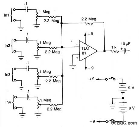
A TL081 op amp is used as a high-to-low impedance converter and signal mixer. The input impedance is approximately 1 megohm and the output impedance is about 1 kilohm. Two 9-volt batteries are used as the power source. Battery life should be several hundred hours with alkaline batteries. (View)
View full Circuit Diagram | Comments | Reading(217)
TWO_MESSAGES_WITH_NlXlES
Published:2009/7/1 21:16:00 Author:May
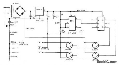
Circuit flashes two messages altemately on same Burroughs giant Nixie B7971 display. Lighted segments needed on individual Nixies to form desired wording are divided into three strings. Segments A are common to both sets of letters and numbers. Segments B are those required with A segments to form first message. Segments C are those required with A segments to form second message. Changeover from segments B to C is done with switching transistors controlled by 555 timer and 7476 or 7473 flipflop. Decimal or other punctuation is formed with NE2 ndon and 100K resistor wired in series between pin 13 of a Nixie and B or C. Article gives construction details.-J. Grimes, Put Your Name in Lights, 73 Magazine, Nov. 1976, p 60-61. (View)
View full Circuit Diagram | Comments | Reading(881)
FOUR_CHANNEL_MIXER_1
Published:2009/6/30 2:16:00 Author:May
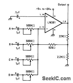
Combines AF signals from one to four sources into single audio signal for input of LM381 opamp that serves also as preamp. Shield mixer circuit and use shielded cable for all input leads to avoid pickup of 60-Hz field by high-gain opamp. Increasing supply voltagefrom minimum of 9V boosts outputsig-nal voltage.-J. A Sandier, 9 Easyto Build Projects under $9, Modern Electronics, July 1978, p 53-56. (View)
View full Circuit Diagram | Comments | Reading(1986)
FOUR_CHANNEL_MIXER
Published:2009/6/30 1:53:00 Author:May
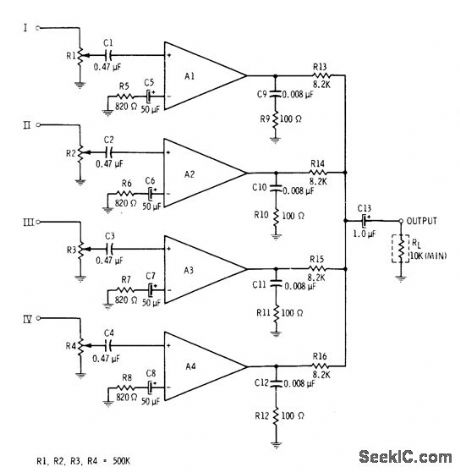
All four sections of RCA CA3048 quad differential amplifier are utilized in linear mixer providing gain of 20 dB for each channel. Designed for use with load of 10K or larger. All inputs are high impedance.-E. M Noll, Linear IC Principles, Experiments, and Projects, Howard VV. Sams, Indianapolis, IN, 1974, p 173 and 179. (View)
View full Circuit Diagram | Comments | Reading(0)
THREE_INPUT_MIXER
Published:2009/6/29 23:46:00 Author:May
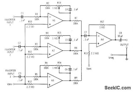
Motorola MC3401P or National LM3900 quad opamp serves for three input amplifiers each having adjustable gain range of 1 to about 11 and input impedance above about 100,000 ohms. Common outputs feed fourth opamp section connected as high-impedance amplifier. Maximum overall gain for mixeramplifier is about 300. Use well-filtered 9-15 V supply or battery capable of supplying 25 mA.-C. D. Rakes, Integrated Circuit Projects, Howard W. Sams, Indianapolis, IN, 1975, p 21-22. (View)
View full Circuit Diagram | Comments | Reading(2691)
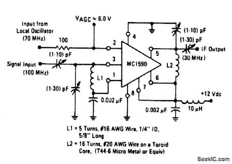
100_MHz_MIXER
Published:2009/6/25 21:34:00 Author:May
View full Circuit Diagram | Comments | Reading(2)
LOCAL_OSCILLATOR_FOR_DOUBLE_BALANCED_MIXERS
Published:2009/6/24 21:19:00 Author:May
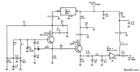
This circuit has an amplifier to supply +10 dBm to an SBL series (Mini-circuits) or similar type doubly-balanced mixer assembly. This circuit has values shown for =80- to 90-MHz crystals, although values of oscillator circuit constants can be scaled for higher or lower frequencies. (View)
View full Circuit Diagram | Comments | Reading(0)
FOUR_CHANNEL_MIXER
Published:2009/6/24 2:23:00 Author:May
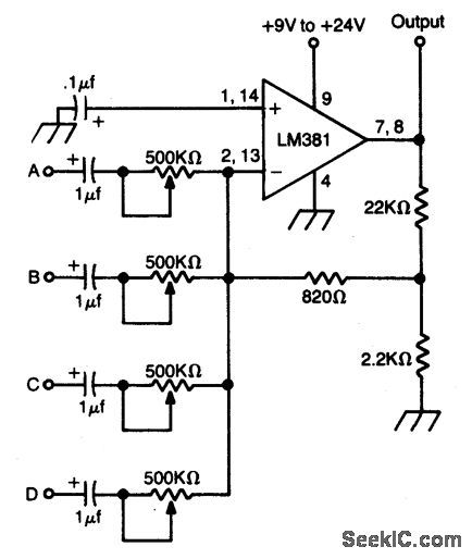
High gain op amp combines up to four individually controlled input signals. The dc power source should be well filtered (battery is ideal), and the circuit should be well shielded to prevent hum pickup. (View)
View full Circuit Diagram | Comments | Reading(2263)
HYBRID_MIXER
Published:2009/6/24 2:22:00 Author:May
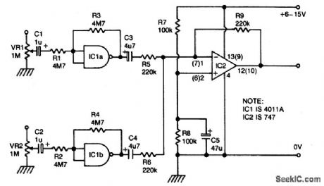
IC1a and b are biased into the linear regions by R3 and R4. (IC1 must be 4011A). Outputs from gates are combined by op amp IC2, which provides low impedance output. (View)
View full Circuit Diagram | Comments | Reading(880)
SILENT_AUDIO_SWITCHING_MIXING
Published:2009/6/24 2:21:00 Author:May

Two or more signals can be switched and/or mixed without annoying clicks by using FETs and a low input-impedance op amp circuit. (View)
View full Circuit Diagram | Comments | Reading(1057)
ONE_TRANSISTOR_AUDIO_MIXER
Published:2009/6/24 2:20:00 Author:May
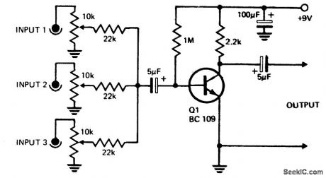
Three or more inputs with individual level controls feed into the base of Q1 that provides a voltage gain of 20. (View)
View full Circuit Diagram | Comments | Reading(1739)
| Pages:2/2 12 |
Circuit Categories
power supply circuit
Amplifier Circuit
Basic Circuit
LED and Light Circuit
Sensor Circuit
Signal Processing
Electrical Equipment Circuit
Control Circuit
Remote Control Circuit
A/D-D/A Converter Circuit
Audio Circuit
Measuring and Test Circuit
Communication Circuit
Computer-Related Circuit
555 Circuit
Automotive Circuit
Repairing Circuit