
Mixer
Index
Audio Mixer with one transistor
Published:2012/9/20 20:59:00 Author:Ecco | Keyword: Audio Mixer , one transistor
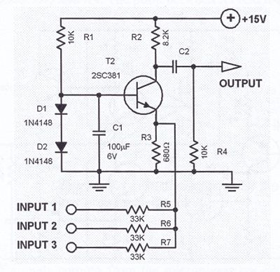
This one transistor audio mixer is used in an amplifier circuit design with base driven transistor and with its emitter being current controlled, most of the driving current flows through the collector away. Using the values in the audio mixer circuit shown in the diagram, the collector current will be about 1 mA. At 15 volts power supply, the input resistors should be 33K. Additional input lines can be connected to the emitter line. Each added input must be series limited by the 33K resistor.
Audio mixer circuit diagram
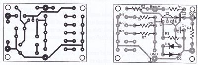
Mixer PCB Layout
(View)
View full Circuit Diagram | Comments | Reading(3446)
One transistor audio mixer (2N3563)
Published:2012/9/10 21:26:00 Author:Ecco | Keyword: One transistor , audio mixer
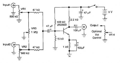
This circuit mixer has an internal amplification with 2N3563 transistor. The two input signals can be independently controlled by VRI and VR2. The VR3 balance control is used to remove a signal while the other melted. (View)
View full Circuit Diagram | Comments | Reading(6046)
4 microphones mixer circuit with TL081
Published:2012/9/10 21:25:00 Author:Ecco | Keyword: 4 microphones
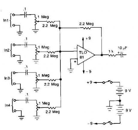
A TL081 op amp is used as a high impedance to low. converter and a signal mixer. The input impedance is about 1 megohm and the output impedance is about 1 kohm. Two 9 volt batteries are used as power source. .. (View)
View full Circuit Diagram | Comments | Reading(0)
4 channel audio mixer with TL074
Published:2012/9/10 21:19:00 Author:Ecco | Keyword: 4 channel , audio mixer
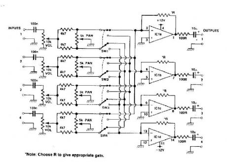
This circuit can be used as a mixer and a stereo track four. The quad op-RNAP IC gives a little gain for each track, the pan control provides panning between one and two tracks with the switch to high, and with the switch to low, it is possible to pan between the tracks and three four channels can be added. (View)
View full Circuit Diagram | Comments | Reading(7997)
TRANSMIT_MIXER
Published:2009/7/13 22:28:00 Author:May
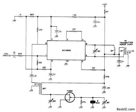
Used in low-power transceiver for 20-meter amateur band. VFO input, tunable from 5 to 5.55 MHz, is combined with 9-MHz output of crystal oscillator in Motorola MC1496G double-balanced modulator to give 14-MHz output for transmitter power chain. Supply voltage (+12 V) is applied only when transmitting. Transformers are wound on Amidon T-50-6 toroids or equivalent. Balance is Balance is maintained in mixer with center-tapped tuned circuit in output, made by putting 15-turn bifilar winding on toroid core and tuning series combination. Article gives all other circuits of transceiver.-W. Hayward, Low-Power Single-Band CW Transceiver, Ham Radio, Nov. 1974, p 8- 1 7. (View)
View full Circuit Diagram | Comments | Reading(2447)
DOUBLE_BALANCED_MIXER
Published:2009/7/13 22:23:00 Author:May
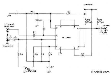
Used in 80-meter SSB transceiver on both transmit and receive. Local oscillator input of 5-5.5 MHz is pro-vided by VFO. SSB signal for receive comes from two-stage MOSFET RF amplifier-D. Hembling, Solid-State 80-Meter SSB Transceiver, Ham Radio, March 1973, p 6-17.
(View)
View full Circuit Diagram | Comments | Reading(0)
MOS_FET_MIXER
Published:2009/7/13 6:13:00 Author:May
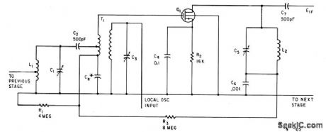
Balanced oscillator input prevents interaction between tuned circuits. Transconductance of mixer is direcdy proportional to oscillator voltage, permitting use for agc. -G. G. Luettgenau and S. H. Barnes, Designing With Low-Noise MOS FETs: A Little Different But No Harder,Electronics,37:31,p53-58 (View)
View full Circuit Diagram | Comments | Reading(1216)
255_MC_OSCILLATOR_MlXER
Published:2009/7/13 5:24:00 Author:May
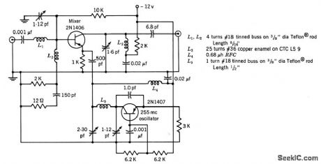
Conversion gain is 20 db and i-f output is 30 Mc.-Texas Instruments Inc. Transistor Circuit Design, McGraw-Hill, N.Y.1963, p326. (View)
View full Circuit Diagram | Comments | Reading(1249)
42O_MC_OSCILLATOR_MIXER
Published:2009/7/13 5:10:00 Author:May
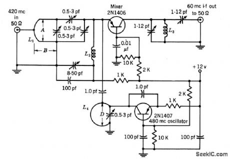
Common-base mixer is used with 480-Mc oscillator to give 60-Mc i-f output, with 10 db average conversion gain.-Texas Instruments Inc. Tran-sistor Circuit Design, McGraw-Hill, N.Y. 1963, p327. (View)
View full Circuit Diagram | Comments | Reading(1411)
CB_TRANSMITTER_MIXER
Published:2009/7/13 4:58:00 Author:May
Requires only one crystal per channel in 27-Mc citizens band radiotelephones, by combining beating oscillator with balanced mixer. Receiver local oscillator with balanced mixer.Receiver local oscilator signal and even harmonics of beating oscillator frequency are cancelled in tuned symmetrical plate circuit.-M. E. Baird, Mixer Circuit Lowers Radiotelephone Costs, Electronics,34:47, p71. (View)
View full Circuit Diagram | Comments | Reading(1364)
BALANCED_INPUT_MIXER
Published:2009/7/13 4:40:00 Author:May


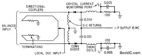
Used with frequency-independent antennas to provide noise cancellation as balanced-input converter.-C. Strother, Jr. and C. R. Lundquist, Balinverter-Frequency-Insensitive Balanced Converter, Electronics, 35:44, p46-47. (View)
View full Circuit Diagram | Comments | Reading(1235)
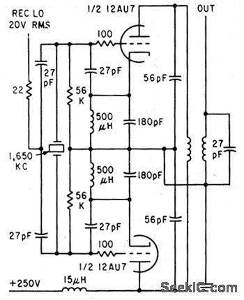
MOTOR_CONTROLLING_MIXER
Published:2009/7/11 2:10:00 Author:May
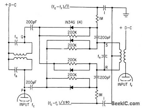
Used to lock crystal oscillator frequency to standard-frequency signals from WWV. Circuit mixes dock and WWV frequencies (fed to tubes at left and right) in Nygaard discriminator ar rangement, which delivers two outputs, each equal to difference frequency but differing 90°in phase. These output signals are amplified for synchronous motor that drives trimmer capacitor of crystal oscillator in servo loop that brings difference frequency to zero.-K.Nygaard, Atomic Clock Accuracy for Crystal Oscillators, Electronics, 33:46, p82-83. (View)
View full Circuit Diagram | Comments | Reading(1065)
SIMPLE_UTILITY_MIXER
Published:2009/7/9 5:07:00 Author:May
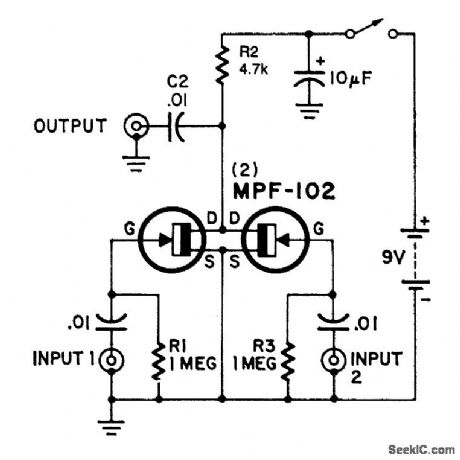

Here's an interesting mixer circuit. With it you can effectively combine signals from audio to high-fre-quency RF. Also, as a special bonus, this circuit will provide some gain at a low noise figure. The inputs can be of almost any level or impedance, and the output (low-Z) will drive most tuned circuits or transistors.Basically, the device consists of two similar FET amplifier stages with a common load resistor (R2). Each FET develops a signal across this resistor, a form of cancellation occurs, and a difference signal results.If you want less gain, try reducing R2 to 2200-Ω. This modification will not affect the mixing ability.
(View)
View full Circuit Diagram | Comments | Reading(2173)
AUDIO_MIXER
Published:2009/7/9 4:58:00 Author:May
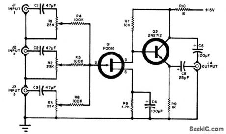
Three audio circuits are combined in the circuit shown. Each input is coupled to its own level potenti-ometer (R1, R2, or R3) and they are combined at the gate of FET Q1. The output of Q1 is coupled to the external audio amplifier through emitter-follower Q2 and capacitor CG. (View)
View full Circuit Diagram | Comments | Reading(0)
4_INPUT_UNITY_GAIN_MIXER
Published:2009/7/9 4:45:00 Author:May
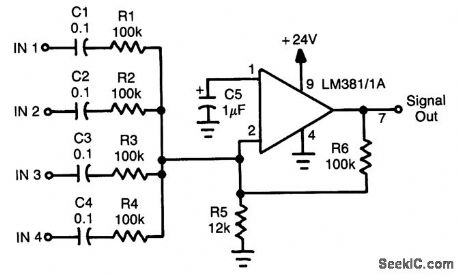
An LM381/1Ais used as a four-input unity-gain audio mlxer. Gain can be increased decreasing R1 through R4 or increasing R6. (View)
View full Circuit Diagram | Comments | Reading(3175)
DIGITAL_MIXER
Published:2009/7/9 4:40:00 Author:May
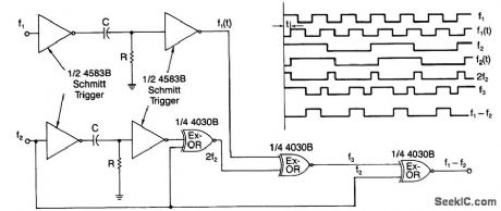
A simple digital mixer, based on two dual-Schmitt triggers (4583B) and three exclusive-OR gates, uses an RC time-delay circuit to permit easy adjustment of the output-signal pulse width. The exclusive-OR gates ,can also be used separately as a symmetrical frequency doublet.As shown, a signal passing through the Schmitt triggers is delayed by t, a value equal to RC In (VTP/VTN)where Vtp and Vtn are the positive and negative threshold voltages of the triggers.To function properly, the same time delay must be introduced to signals f1 and f2. Also, the time delay must be less than 50%of the period of f1. Provided that f1 is more than twice the value of f2, the output of the circuit will equal the difference of the two signals (i.e., f1 - f2). (View)
View full Circuit Diagram | Comments | Reading(2586)
_4_CHANNEL_MIXERV
Published:2009/7/9 3:07:00 Author:May

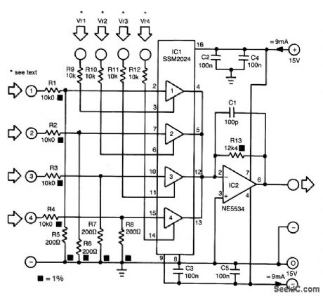


The proposed mixer is designed around four current-driven transconductance amplifiers contained in an SSM2024 from Precision Monolithics. To obtain a low offset and high control rejection, the four inputs should have an impedance to earth of about 200 Ω . These impedances are obtained from resistors R5 through R8, which also form part of a potential divider at each input.With the values in the diagram, the nominal input signal is 1 V (0 dBV). Distortion at that level is about 1%; at lower levels, it is not more than 0.3%.
The amplification of the current-driven amplifiers (CDAs) is determined by the current fed into the control inputs. These inputs form a virtual earth so that calculating the values of the bias resistors (to transform the inputs into voltage-driven inputs) is fairly simple.The output currents of the amplifier are summed by simply linking the output pins. The current-to-voltage convener, IC2, translates the combined output currents into an output voltage. The value of R13 ensures that the amplification of IC2 is unity. (View)
View full Circuit Diagram | Comments | Reading(1960)
UNIVERSAL_MIXER_STAGE
Published:2009/7/8 4:30:00 Author:May
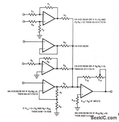
This circuit illustrates some possible buffer combinations. These include a differential input stage, a voltage follower as well as both noninverting and inverting stages. The allowable resistor ratios and recommended device types are also included. One restriction applies to this type of mixer network in which Rg is greater than 2.4 KΩ. This limits the worst case output current for each of the input buffers to less than 10 mA.
(View)
View full Circuit Diagram | Comments | Reading(1079)
FOUR_CHANNEL_MIXER
Published:2009/7/8 4:28:00 Author:May
View full Circuit Diagram | Comments | Reading(0)
INPUT_BUFFERED_MIXER
Published:2009/7/8 4:27:00 Author:May
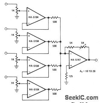
A high signal-to-noise ratio is important in stgnal construction and combination. The HA-5147 aids in lowering overall system noise and thereby raises system sensitivity. The signal combination circuit incorporates input buffering with several other features to form a relatively efficient mixer stage with a minimum of channel crosstalk. The potentiometer used for each channel allows for both variable input levels and a constant impedance for the driving source. The buffers serve mainly to prevent reverse crosstalk back through the resistor network. This buffering allows for the combination of varying strength signals without reverse contamination. The gain of the final stage is set at a minimum of 10 and can be adjusted to as much as 20.This allows a great amount of flexibility when combining a vast array of input signals. (View)
View full Circuit Diagram | Comments | Reading(1349)
| Pages:1/2 12 |
Circuit Categories
power supply circuit
Amplifier Circuit
Basic Circuit
LED and Light Circuit
Sensor Circuit
Signal Processing
Electrical Equipment Circuit
Control Circuit
Remote Control Circuit
A/D-D/A Converter Circuit
Audio Circuit
Measuring and Test Circuit
Communication Circuit
Computer-Related Circuit
555 Circuit
Automotive Circuit
Repairing Circuit